19
The
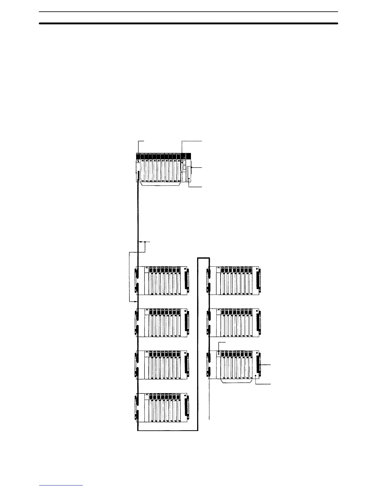
following figure shows an assembled CV
-series CPU Rack
and seven C500
Expansion I/O Racks. Up to seven C500 Expansion I/O Racks may be con-
nected
to the CPU Rack. The total length of the I/O Connecting Cable must 5 m
or less and each section of I/O Connecting Cable must be 2 m or less. T
ermina-
tion Resistance Units are not necessary.
Expansion
I/O Racks for the CV
-series
cannot be used together with C500 Ex
-
pansion I/O Racks.
Units can be mounted to any slot on the Racks shown for them below.
I/O
Control Unit
CV500-IC301
I/O Connecting Cable C500-CN
jj
2N
(2 m max. each cable, 5 m max. total length)
8 or 5 slots
C500 I/O Units
C500 Special I/O Units
SYSMAC BUS Masters
I/O Backplane
3G2A5-BI081/BI051
Power Supply Unit
3G2A5-PS222-E/PS212
I/O Interface Unit
3G2A5-II002
(T
erminal Resistance Units are not required.)
CPU Backplane: CV500-BC031/051/101
Power Supply Unit: CV500-PS221/PS21
1 or
CVM1-PA208
CPU: CV500-CPU01-EV1, CV1000-CPU01-EV1,
CV2000-CPU01-EV1, CVM1-CPU01-EV2,
CVM1-CPU1
1-EV2, or CVM1-CPU21-EV2
3, 5, or 10 slots
SYSMAC NET Link Units
SYSMAC LINK Units
SYSMAC BUS/2 Masters
Personal Computer Units
BASIC Units
C500 I/O Units
C500 Special I/O Units
SYSMAC BUS Masters
Systems with C500
Expansion I/O Racks
System Configuration Section 2-1

 Loading...


