55
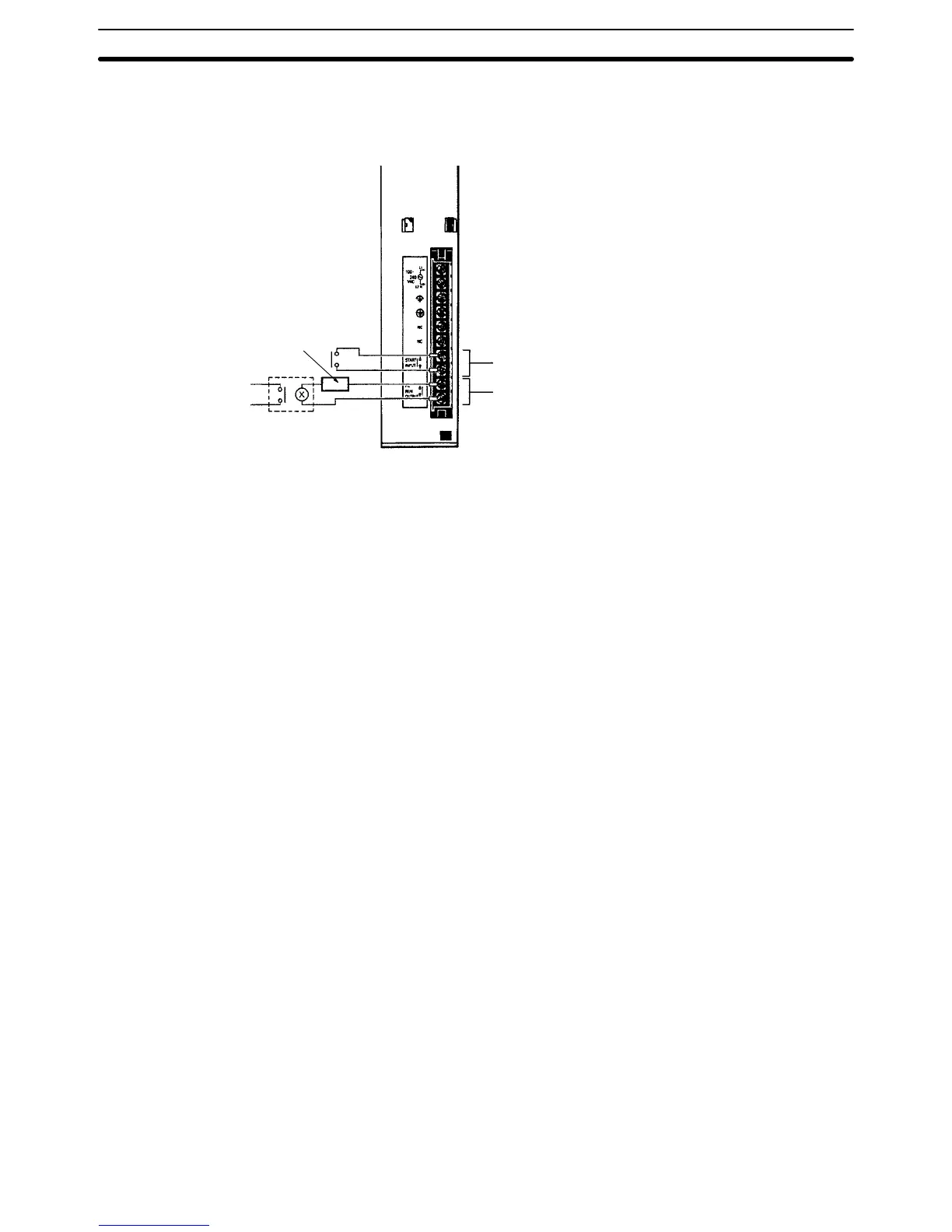
3-4-3 Wiring Other Terminals
The
Power Supply Units provide a ST
AR
T input and a RUN output. These termi
-
nals can be used to help control system operation.
START
input
(CPU Racks only)
24 V
,10 mA
RUN output (all Racks)
Maximum Switching Capacity:
250 V
AC: 2 A (resistive load, cosf
= 1)
250 V
AC:
0.5 A (inductive load, cos
f
= 0.4)
24 VDC:
2 A
To
system
con
-
trol circuits
Emergency
stop circuit
Power supply
Note 1. Use
reinforced insulation or double insulation on the DC power supply con
-
nected
to CV500-PS21
1 Power Supply Unit when complying
with EC direc
-
tives (low voltage).
2. The
maximum switching capacity of the CV500-PS21
1 Power Supply Unit
is
2
A at 24 VDC when complying with EC Directives (low-voltage directives).
START Input The
ST
AR
T input terminals are short-circuited at the factory with a short bar
. The
short
bar can be removed and the terminals wired to a 10-mA, 24-VDC external
input
to control PC operation. When these terminals are open, PC operation will
stop.
RUN Output The
RUN
output terminals will be ON (closed) when the PC is operating in RUN
or MONIT
OR mode. These terminals can thus be
wired to provide an external
signal
indicating the operating status of the PC, such as is used in the emergen
-
cy stop circuit in the next section.
Power Supply Units Section 3-4

 Loading...


