57
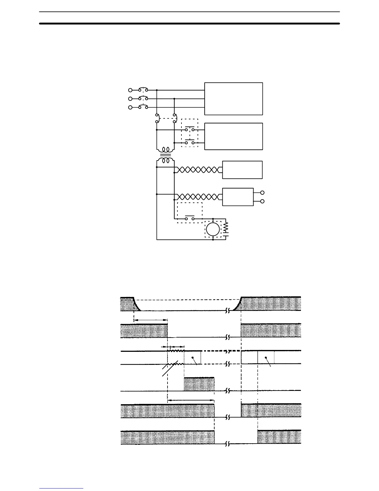
3-4-4 Emergency Stop
You
can use an external relay (CR in the following figure) to form an emergency
stop
circuit that shuts down the system when PC
operation stops. This can be
achieved
by wiring the RUN output from the Power Supply Unit on the CPU Rack
as shown below.
MCB1
MCB2
CR1
Power supply
Control section
DC voltage
regulator
Transformer
or noise filter
Twisted-pair wires
PC RUN
output
+
–
DC
input/output
CR1 Surge suppressor
PC
3-4-5 Power Interruptions
A
sequence circuit is built into the PC to
handle power interruptions. This circuit
prevents
malfunctions due to momentary power loss or voltage drops. A timing
diagram for the operation of this circuit is shown below.
Power supply
Power interrup
-
tion detection
signal
Program execution
Momentary Power
Interruption Flag
(A40202)
CPU reset signal
RUN output
*
0.3 to 1 ms for DC power
.
85%
Power interruption
power
interruption detection time: 10 to 25 ms*
Shutdown processing
Momentary
power inter
-
ruption time (default: 0 ms)
Initialization
NormalNormal
Stops
Standby
Power
retention time: 10 ms (fixed)
Power OFF
interrupt program
Power-ON
interrupt program
Power Supply Units Section 3-4

 Loading...


