63
When
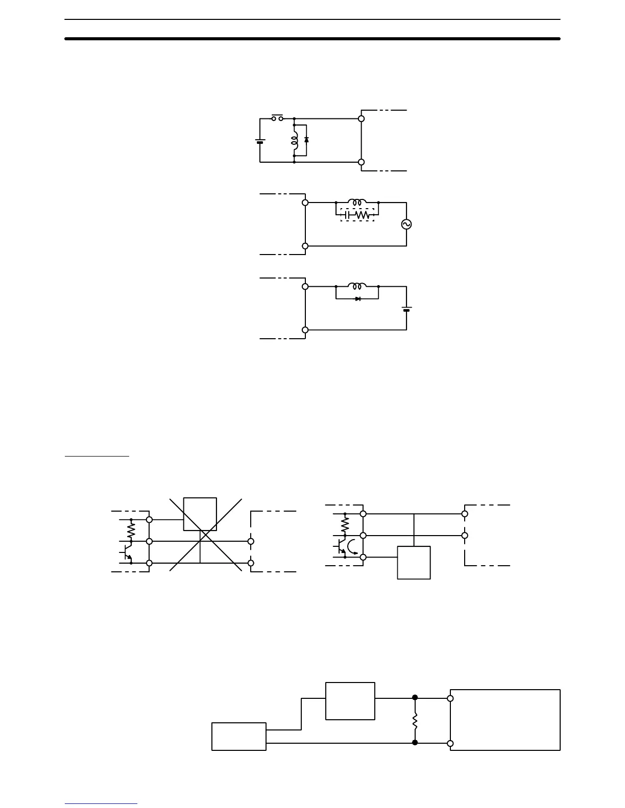
an inductive load is connected to an I/O Unit, connect a surge suppressor
or
diode in parallel with the load, as shown in the following diagram. The diode
will adsorb the back electromagnetic field generated by the load.
L
IN
COM
Diode DC
input
OUT
COM
Relay Output Unit
T
riac Output Unit
OUT
COM
Relay Output Unit
T
ransistor Output Unit
Diode
L
L
+
Surge suppressor
where for the surge suppressor
,
Resistor:
50
W
Capacitor:0.47F
Voltage:
200 V
and the diode,
Breakdown voltage: at least 3 times load voltage
Mean rectification current: 1 A
Input Units
Voltage Inputs Do not wire voltage inputs as shown on the left below.
+
0
V
Sensor
power
supply
V
oltage output
Output
COM (–)
IN DC input
Incorrect
+
0 V
Sensor
power
supply
V
oltage output
Output
COM (+)
IN DC input
Correct
Input Leakage Current When two-wire sensors, such as photoelectric sensors, proximity sensors or
limit
switches with
indicators are connected to the PC as input devices, the input
bit
may be turned ON erroneously by leakage current. In order to prevent this,
connect a bleeder resistor across the input to reduce the input impedance.
Sensor
Input
power
supply
Bleeder
resistor
R
PC
Inductive Load Surge
Suppressor
Wiring I/O Units Section 3-5

 Loading...


