D2F
D2F
201
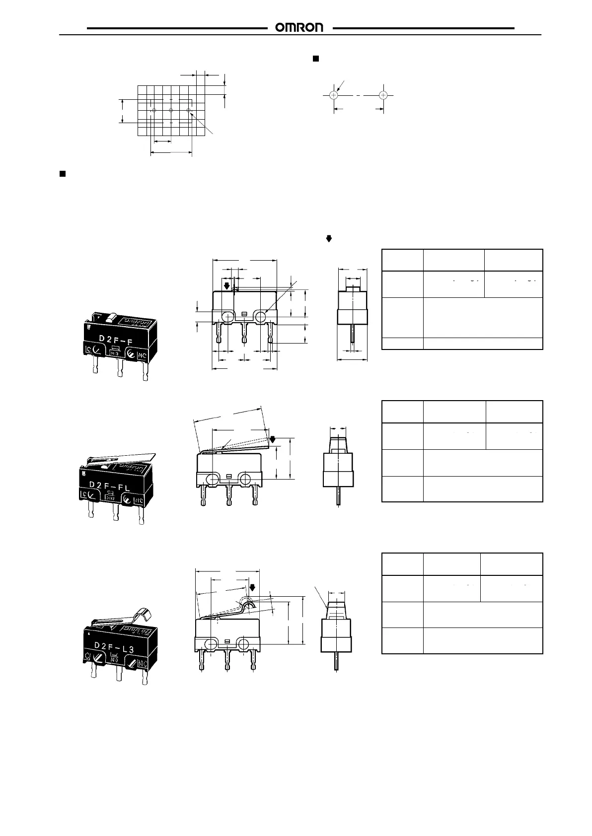
PCB Mounting Dimensions
(Reference)
2.54
2.54
12.8 ± 0.15
5.08 ± 0.1
5.8 ± 0.15
Three,
1.2 dia. holes
Mounting Holes
Two , 2-dia. mounting holes
6.5 ± 0.15
Dimensions and Operating Characteristics
Note: 1. All units are in millimeters unless otherwise indicated.
2. Unless otherwise specified, a tolerance of ±0.4 mm applies to all dimensions.
3. The following illustrations and drawings are for D2F models with PCB terminals. Self-clinching, solder, and right-angled, left-angled
terminals are omitted from the following drawings. Refer to page 200 for these terminals. When ordering, replace j with the code for
the terminal that you need.
4. The operating characteristics are for operation in the A direction (
).
Model
D2Fj
D2F-01j
D2F-Fj
D2F-01Fj
OF max. 1.47 N {150 gf} 0.74 N {75 gf}
RF min.
0.20 N {20 gf}
0.05 N {5 gf}
PT max. 0.5 mm
OT min. 0.25 mm
MD max. 0.12 mm
OP 5.5±0.3 mm
Model
D2F-Lj
D2F-01Lj
D2F-FLj
D2F-01FLj
OF max. 0.78 N {80 gf} 0.25 N {25 gf}
RF min.
0.05 N {5 gf}
0.02 N {2 gf}
OT min. 0.55 mm
MD max. 0.5 mm
FP max. 10 mm
OP
6.8±1.5 mm
Model
D2F-L3j
D2F-01L3j
D2F-FL3j
D2F-01FL3j
OF max. 0.78 N {80 gf} 0.39 N {40 gf}
RF min.
0.05 N {5 gf}
0.02 N {2 gf}
OT min.
MD max.
0.5 mm
0.45 mm
FP max. 13 mm
OP 8.5±1.2 mm
Pin Plunger Models
D2Fj
D2F-01j
D2F-Fj
D2F-01Fj
2.2
+0.12
0 dia.
2
+0.12
0
dia. holes
12.7
1.2
5.2
5OP
1.5
3.5
0.9
0.4
5.8±0.15
12.8±0.15
5.08 5.08
6.5±0.1
3.15
5.7
2.9
2
+0.12
0
PT
A
Hinge Lever Models
D2F-Lj
D2F-01Lj
D2F-FLj
D2F-01FLj
t = 0.3 (see note)
12.8
(10.8)
OP
FP
3
Note: Stainless-steel lever
A
Simulated Roller Lever Models
D2F-L3j
D2F-01L3j
D2F-FL3j
D2F-01FL3j
t = 0.3 (see note)
1.3R
12.7
(7.5)
10
2.1
OP
FP
3
Note: Stainless-steel lever
A