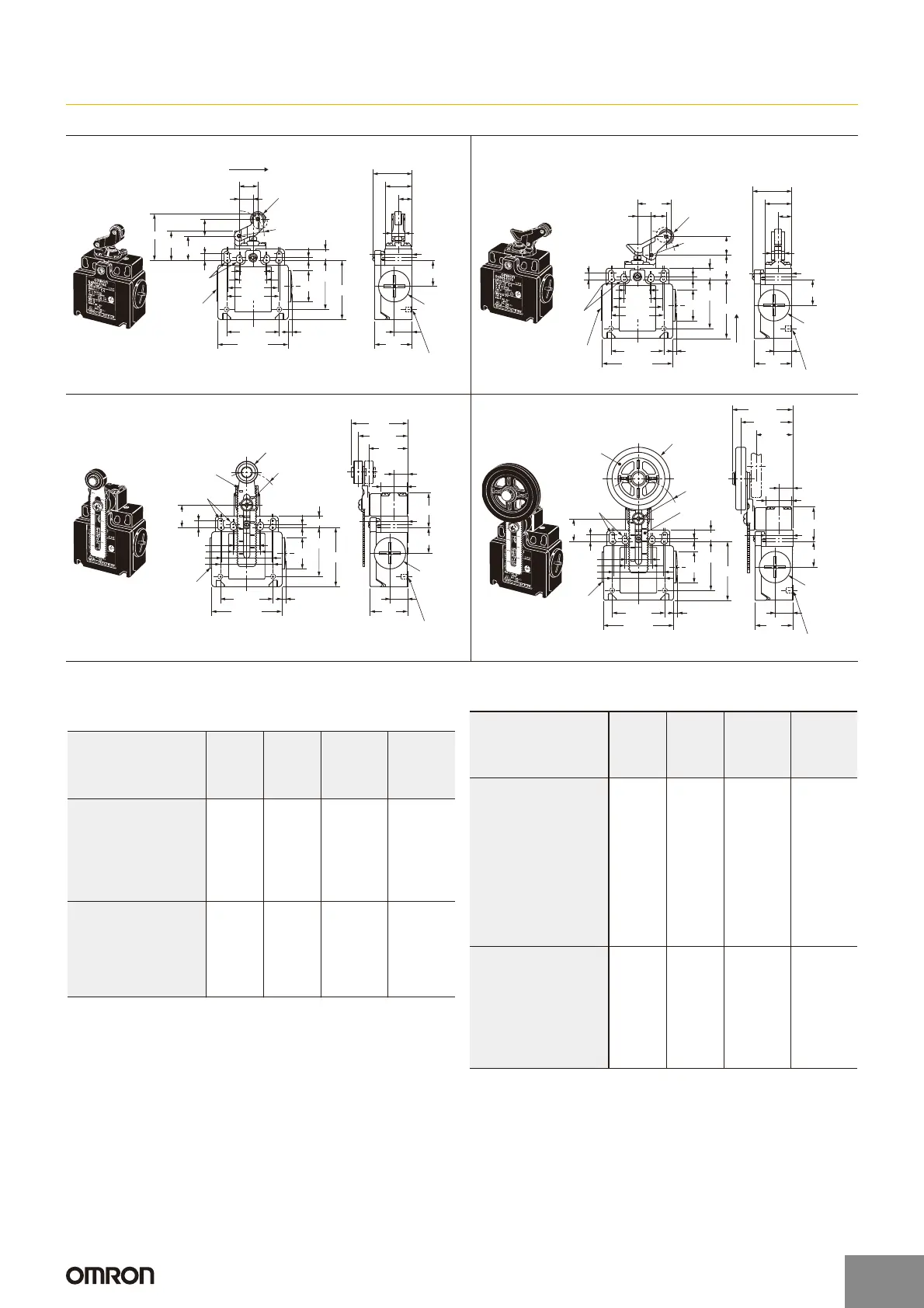
D4N
2-conduit Models
Note: Unless otherwise specified, a tolerance of r0.4 mm applies to all dimensions.
v
Two, 4
+0.15
dia. holes
Depth: 5
0
One-way Roller Arm Lever
(Horizontal)
D4N-5@62
D4N-6@62
D4N-8@62
12 dia. x 5
resin roller
2.15±0.05R
mounting holes
30
Cap
20.5
21.5
42
±0.2
(3)
56 max.
47
25 dia.
2.5
5.4
9
±0.2
20
±0.1
40
±0.1
42
±0.1
22
±0.1
14.2
11
±0.2
10.2
(31.5)
14.8
Operating direction
23.3
13.5
11
±0.2
19.5
±0.2
20R
OP
21.5
39
±0.2
Conduit cap
Two, 4
+0.15
dia. holes
Depth: 5
0
One-way Roller Arm Lever
(Vertical)
D4N-5@72
D4N-6@72
D4N-8@72
Operating
direction
12 dia. × 5
resin roller
30
Cap
20.5
21.5
42
±0.2
(3)
56 max.
47
25 dia.
2.5
5.4
9
±0.2
20
±0.1
40
±0.1
42
±0.1
22
±0.1
14.2
OP
14.7
19R
19.5
±0.2
11
±0.2
12
11
±0.2
10.2
(31.5)
21.5
39
±0.2
2.15±0.05R
mounting
holes
Conduit cap
Adjustable Roller Lever, Form Lock
(with Metal Lever, Resin Roller)
D4N-6@2G
D4N-8@2G
17.5 dia. × 6.8
resin roller
Two, 4
+0.15
dia. holes
Depth: 5
0
30
Cap
27.5
20.5
11
±0.2
21.5
42
±0.2
(3)
56 max.
47
25 dia.
2.5
5.4
9
±0.2
18
20
±0.1
40
±0.1
42
±0.1
22
±0.1
14.2
45
±1
39.5
±1
(31)
39
±0.2
20 to 66RResin lever
2.15±0.05R
mounting holes
Conduit cap
20.5 × 20.5
Adjustable Roller Lever, Form Lock
(with Metal Lever, Rubber Roller)
D4N-6@2H
D4N-8@2H
50 dia. × 8
rubber roller
Bearing
Stainless
steel lever
Two, 4
+0.15
dia. holes
Depth: 5
0
20.5 × 20.5
30
Cap
27.5
20.5
11
±0.2
21.5
42
±0.2
(3)
56 max.
47
25 dia.
2.5
5.4
9
±0.2
18
20
±0.1
40
±0.1
42
±0.1
22
±0.1
14.2
48.2
±1
41.3
±1
(29.2)
39
±0.2
32 to 66R
2.15±0.05R
mounting holes
Conduit cap
Snap-action (1NC/1NO) (2NC), Slow-action (2NC)
(3NC)
Note: Variation occurs in the simultaneity of contact opening/closing operations
of 2NC, 2NC/1NO, and 3NC contacts. Check contact operation.
*1. The operating characteristics of these Switches were measured with the roller
lever set at 30 mm.
*2. The operating characteristics of these Switches were measured with the roller
lever set at 31 mm.
*3. Only for snap-action models.
*4. Reference value.
*5. For safe use, always make sure that the minimum values or greater are
provided.
Model
Operating characteristics
D4N-@162
D4N-@262
D4N-
@
B62
D4N-
@
D62
D4N-@172
D4N-@272
D4N-
@
B72
D4N-
@
D72
D4N-@12G
D4N-@22G
D4N-@B2G
D4N-@D2G
*1
D4N-@12H
D4N-@22H
D4N-@B2H
D4N-@D2H
*2
Operating force
OF max. 5.0 N5.0 N4.5 N 4.5 N
Release force RF min. 0.8 N 0.8 N 0.4 N 0.4 N
Pretravel PT max. 4 mm 4 mm 18q to 27q 18q to 27q
Overtravel
OT min.
5 mm 5 mm 40q 40q
Movement differential
MD max. *3
1.5 mm 1.5 mm 14q 14q
Operating position
OP
37
r
0.8 mm 27
r
0.8 mm
--- ---
Total travel TT *4 (9 mm) (9 mm) (70q)(70q)
Direct opening travel
DOT min. *5
5.8 mm 4.8 mm 50q 50q
Direct opening force
DOF min. *5
20 N 20 N 20 N 20 N
Slow-action (1NC/1NO) (2NC/1NO)
*1. The operating characteristics of these Switches were measured with the roller
lever set at 30 mm.
*2. The operating characteristics of these Switches were measured with the roller
lever set at 31 mm.
*3. This PT value is possible when the NC contacts are open (OFF).
*4. This PT value is possible when the NO contacts are closed (ON).
*5. Only for MBB models.
*6. Reference value for MBB models only.
*7. Only for MBB models.
*8. Reference value.
*9. For safe use, always make sure that the minimum values or greater are provided.
Model
Operating characteristics
D4N-
@
A62
D4N-
@
C62
D4N-
@
E62
D4N-@F62
D4N-
@
A72
D4N-
@
C72
D4N-
@
E72
D4N-@F72
D4N-@A2G
D4N-@C2G
D4N-@E2G
D4N-@F2G
*1
D4N-@A2H
D4N-@C2H
D4N-@E2H
D4N-@F2H
*2
Operating force OF max.
5.0 N 5.0 N 4.5 N 4.5 N
Release force RF min. 0.8 N 0.8 N 0.4 N 0.4 N
Pretravel PT max.
*3
4 mm 4 mm 18q to 27q 18q to 27q
PT (2nd)
*4
(5.2 mm) (4.3 mm) (44q)(44q)
PT max.
*5
4 mm 4 mm
27.5
q
to 36.5
q
27.5
q
to 36.5
q
PT (2nd)
*6
(1.5 mm) (1.5 mm) (18q)(18q)
Overtravel OT min. 5 mm 5 mm 40q 40q
Operating position
OP
37
r
0.8 mm 27
r
0.8 mm
--- ---
OP *7
36
r
0.8 mm
26.1
r0.8 mm
--- ---
Total travel TT *8 (9 mm) (9 mm) (70q)(70q)
Direct opening travel
DOT min. *9
5.8 mm 4.8 mm 50q 50q
Direct opening force
DOF min. *9
20 N 20 N 20 N 20 N
http://www.ia.omron.com/
15
(c)Copyright OMRON Corporation 2007 All Rights Reserved.

 Loading...