D4N
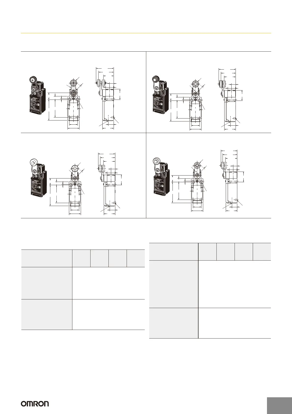
Dimensions and Operating Characteristics (Unit: mm)
Switches
1-conduit Models
Note: Unless otherwise specified, a tolerance of r0.4 mm applies to all dimensions.
* Refer to page 12 for details on M12 connectors.
Roller Lever (Resin Lever, Resin Roller)
D4N-1@20 D4N-2@20
D4N-3@20 D4N-4@20
D4N-9@20 *
17.5 dia. × 6.8
resin roller
Two, 4
+0.15
dia. holes
Depth: 5
0
30
27.5
11
±0.2
47
±1
40
±1
(27)
21.5
22
±0.2
31 max.
55
47
±0.2
2.5
9
±0.2
26R
18
20
±0.1
22
±0.1
14.2
Resin lever
2.15±0.05R
mounting holes
Conduit cap
20.5 × 20.5
Roller Lever (Metal Lever, Resin Roller)
D4N-1@22 D4N-2@22
D4N-3@22 D4N-4@22
D4N-9@22 *
17.5 dia. × 6.8
resin roller
Two, 4
+0.15
dia. holes
Depth: 5
0
30
27.5
11
±
0.2
45±
1
39.5±
1
(31)
21.5
22±
0.2
31 max.
55
47±
0.2
2.5
9±
0.2
26R
18
20±
0.1
22±
0.1
14.2
Metal lever
2.15±0.05R
mounting holes
Conduit cap
20.5 × 20.5
Roller Lever (Metal Lever, Metal Roller)
D4N-1@25 D4N-2@25
D4N-3@25 D4N-4@25
D4N-9@25 *
17.5 dia. × 7
sintered stainless
steel roller
Two, 4
+0.15
dia. holes
Depth: 5
0
30
27.5
11
±
0.2
45±
1
39.5±
1
(31)
21.5
22±
0.2
31 max.
55
47±
0.2
2.5
9±
0.2
26R
18
20±
0.1
22±
0.1
14.2
Metal lever
20.5 × 20.5
2.15±0.05R
mounting holes
Conduit cap
Roller Lever (Metal Lever, Bearing Roller)
D4N-1@26 D4N-2@26
D4N-3@26 D4N-4@26
D4N-9@26 *
17 dia. × 6
Bearing roller
Two, 4
+0.15
dia. holes
Depth: 5
0
Metal lever
20.5 × 20.5
2.15±0.05R
mounting holes
Conduit cap
30
27.5
11
±
0.2
43.6±
1
39±
1
(31.5)
21.5
22±
0.2
31 max.
55
47±
0.2
2.5
9±
0.2
26R
18
20±
0.1
22±
0.1
14.2
Snap-action (1NC/1NO) (2NC), Slow-action (2NC)
(3NC)
Note: Variation occurs in the simultaneity of contact opening/closing
operations of 2NC, 2NC/1NO, and 3NC contacts. Check contact
operation.
*1.Only for snap-action models.
*2.Reference value.
*3.For safe use, always make sure that the minimum values or greater
are provided.
Model
Operating characteristics
D4N-@120
D4N-@220
D4N-
@
B20
D4N-
@
D20
D4N-@122
D4N-@222
D4N-
@
B22
D4N-
@
D22
D4N-@125
D4N-@225
D4N-
@
B25
D4N-
@
D25
D4N-@126
D4N-@226
D4N-
@
B26
D4N-
@
D26
Operating force OF max. 5.0 N
Release force RF min. 0.5 N
Pretravel PT 18q to 27q
Overtravel OT min. 40q
Movement differential MD max.
*1
14q
Operating position OP ---
Total travel TT *2 (80q)
Direct opening travel DOT min.
*3
50q
Direct opening force DOF min.
*3
20 N
Slow-action (1NC/1NO) (2NC/1NO)
*1. These PT values are possible when the NC contacts are open (OFF).
*2. These PT values are possible when the NO contacts are closed (ON).
*3.Only for MBB models.
*4.Reference values for MBB models only.
*5.Reference values.
*6.For safe use, always make sure that the minimum values or greater
are provided.
Model
Operating characteristics
D4N-
@
A20
D4N-
@
C20
D4N-
@
E20
D4N-@F20
D4N-
@
A22
D4N-
@
C22
D4N-
@
E22
D4N-@F22
D4N-
@
A25
D4N-
@
C25
D4N-
@
E25
D4N-@F25
D4N-
@
A26
D4N-
@
C26
D4N-
@
E26
D4N-@F26
Operating force OF max. 5.0 N
Release force RF min. 0.5 N
PT *1 18q to 27q
PT (2nd)
*2
(44q)
PT *3 27.5q to 36.5q
PT (2nd)
*4
(18q)
Overtravel OT min. 40q
Operating position OP ---
Total travel TT *5 (80q)
Direct opening travel DOT min.
*6
50q
Direct opening force DOF min.
*6
20 N
http://www.ia.omron.com/
9
(c)Copyright OMRON Corporation 2007 All Rights Reserved.
 Loading...