3
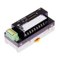
DRT2-ID16/OD16
DRT2-ID16/OD16
For more information, contact an Omron representative at 1-800-55-OMRON
■
Operating Time Monitor Function
Errors in machine operation can be detected by measuring
the time interval between output and input.
The Slave can perform high-speed measurement of the interval
between the time an output is turned ON by a specified bit and the
time an input is turned ON. It is possible to read this measurement
result (between 2 and 65,535 ms) using the Configurator or explicit
message communications. This feature contributes to preventive
maintenance by allowing the detection of mechanical deteriora-
tion, such as air leaks in cylinders. A threshold value can also be
set in the Slave so that a flag turns ON when the time becomes
longer than a set time.
■
Contact Operation Counter Function
Provides notification of maintenance timing for I/O devices,
such as switches and actuators.
This function provides notification of maintenance timing for input
and output devices, such as switches and actuators.
■
Energized Time Monitor Function
Every six minutes the Slave records the total energized time of, for
example, a motor. This record can be read using the Configurator
or explicit message communications.
MS NS NODE ADDRESS
DRT2-ID16
ET-OD16
Measurement
time
Measurement
time
Smart Slave
Output contact A
(e.g., valve)
Output contact A
(e.g., valve)
Input contact B
(e.g., sensor)
Recorded in
the Slave
Measurement
time
Input contact B
(e.g., sensor)
Note: This function can only be used when combinations of
Basic Units and Expansion Units that have both inputs
and outputs are used.
MS NS NODE ADDRESS
DRT2-ID16
1 2 3
Number
of times
OFF to ON
Output device
(e.g., relay)
Counts the number
of OFF to ON
operations
Smart Slave
Recorded in
the Slave
MS NS NODE ADDRESS
DRT2-ID16
Smart Slave
Total conduction
time
I/O power
supply
Motor
Motor's
conduction time
Total conduction
time
Recorded in
the Slave
Note: The contact operation counter function and the unit conduction time monitor
function cannot be used simultaneously.
 Loading...