F3W-D
8
8
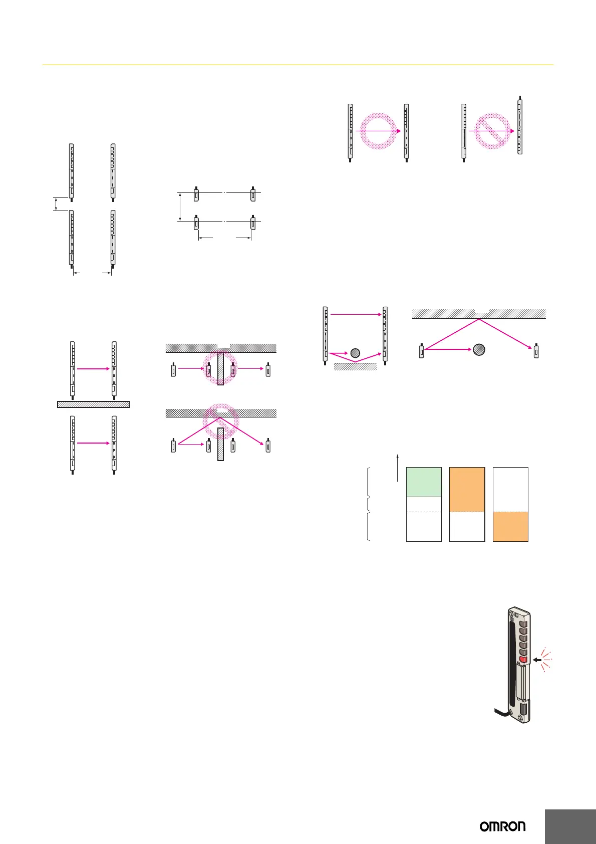
• The distance between two adjacent sets of Sensors must be at
least l
1 or l2, which does not cause mutual interference between two
Sensors with the same frequency setting. l
1 or l2 is at least 1.5 times
the distance shown in Parallel Operating Range of the Engineering
Data.
• Install a baffle so that there will not be mutual interference between
Sensors with the same frequency setting. (See Figure 1.)
A light reflection from the wall or floor may go around a baffle and
reach the Receivers. Install a baffle so that it will also block any light
reflection. (See Figure 2.)
● Wiring Precautions
Connection
• Before turning ON the power, make sure that the supply voltage is
within the maximum allowable voltage range.
• Always connect the sync lines.
• Be very careful not to get metal chips in the connector, especially
during wiring.
• Incorrect wiring may damage the equipment. Make sure that the
cable length and routing are appropriate to prevent the connectors
and cables from getting disconnected.
• Always leave the operation cover closed during operation.
Cables
Make sure that the bending radius is 25 mm or more.
● Installation Precautions
Installation
• Install the Sensor so that its sensing face will not receive light from
the sun, fluorescent lamps, incandescent lamps, and other light
sources.
• Do not strike the Sensor with a hammer or any other tool during
installation, otherwise the internal circuits of the Sensor may be
damaged.
• Install the Emitter and Receiver in the same orientation as shown in
the following figure. (The cables must be in the same direction.)
• Use M4 screws to secure the Sensor body.
• Secure the case to a tightening torque of 1.2 N·m or less.
• Be very careful not to drop the Sensor or screws when securing the
Sensor above eye level.
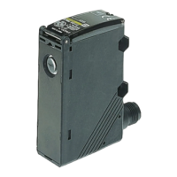
• Do not install the Sensor in reflective configuration.
Reflection from Wall or Floor
If the Emitter and Receiver are installed as shown in the following
illustration, all the axes may not be interrupted due to light reflection
from the floor or wall. Make sure that the Emitter and Receiver detect
the sensing object properly before using the F3W-D in actual
operation.
Side View Top View
● Adjustment
Operation and Stability Status Display
• The following illustration shows the indicator status corresponding
to each incident level.
• Install the Receiver so that the green stability indicators are both
ON in light receiving status.
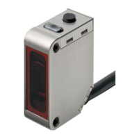
Error Display
F3W-D052 Picking Sensors are provided with only
one error display mode.
If an error occurs, the indicator on the Sensor’s
Receiver, as indicated by the arrow in the diagram
on the right, will flash.
The error indicated in this example is a
synchronization error.
The possible causes are as follows:
1. The sync line is not connected.
2. The sync line is shorted with another line.
Emitter
l
2
Receiver
Emitter Receiver
Distance X
Vertical Installation
Horizontal Installation
l1
Distance X
ReceiverEmitter
ReceiverEmitter
Emitter Receiver Emitter Receiver
Baffle
Wall
Emitter Receiver Emitter Receiver
Baffle
Figure 2
Wall
ReceiverEmitter
ReceiverEmitter
Baffle
Figure 1
Emitter Receiver Emitter Receiver
Sensing object
Floor
Light reflection
Wall
Emitter Receiver
Emitter Receiver
Light-shielded area
Unstable light-
receiving area
Stable light-
receiving area
*
Operating level
× 1.2
Operating level
Stability indicator
(green)
* If the Receiver is set to the stable light-receiving area, it will become more
resistant to environmental fluctuations such as temperature, voltage, dust, and
setting deviation after installation. For applications where a stable light-receiving
area is not obtained, attention must be paid to environmental fluctuations.
Operation indicator (orange)
Light-ON Dark-ON
ON
OFF
ON
OFF
ON
OFF
Amount of
light received