F3W-D
5
5
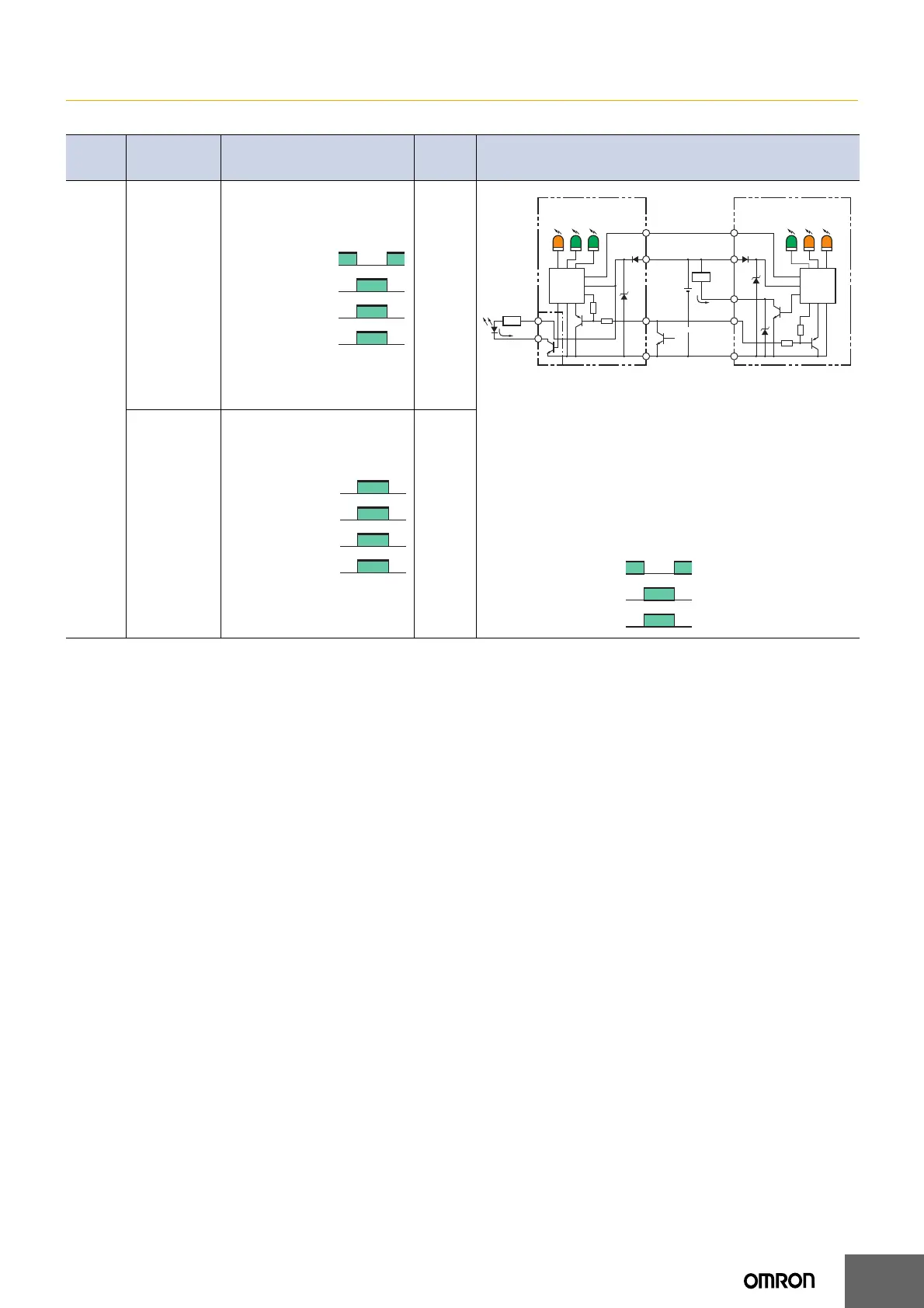
I/O Circuits
NPN Open-collector Outputs
Model
Operation
mode
Timing chart
Mode
selector
switch
Output circuit
F3W
-D052A
F3W
-D052AP
F3W
-D052B
F3W
-D052BP
Dark-ON mode
ON:
One beam
or more is
interrupted
OFF:
No beam is
interrupted
D-ON
(DARK
ON)
Note: The circled numbers represent the pin numbers for Pre-wired Connector
Models.
*1. The sections surrounded by single-dashed lines are applicable to the F3W-
D052AP-L/BP-L only.
*2. The circled numbers represent external picking indicator output pin
numbers.
The following diagram shows the relationship between the picking in-
struction input, picking indicator status, and external picking indicator
output. DIP switch 1 is used to switch the picking display mode be-
tween all lighting, all flashing, elevator-like lighting, and accordion-
like lighting. It is also possible to switch the external picking indicator
display mode between lighting and flashing.
Light-ON mode
ON:
No beam is
interrupted
OFF:
One beam
or more is
interrupted
L-ON
(LIGHT
ON)
No beam is interrupted
One beam or more is interrupted
ON
OFF
ON
OFF
Operate
Reset
Operation indicator
(orange)
Light
incident
Control output
Load (relay, etc.)
5
1
2
3
Six
picking
indicators
(orange)
Power
indicator
(green)
Different
frequency
indicator
(green)
F3W-D052A@-L/B@-L F3W-D052A@-D/B@-D
Emitter
main
circuit
Six picking
indicators
(orange)
Operation
indicator
(orange)
Stability
indicator
(green)
Receiver
main
circuit
5 V
5 V
Orange/purple
stripe
Orange/purple
stripe
12 to 24
VDC
External picking
indicator output
Brown
Pink
Blue
5
1
2
3
Brown
Brown
Blue
*1
*2
*2
Pink
100 mA
max.
Blue
Load
4
2
1
Load
50 mA max.
(Sync line)
(Control
output)
Black
Picking
instruction
input
Open
0 V
ON
OFF
ON
OFF
Picking indicator
(orange)
External picking
indicator output
Picking instruction
input
No beam is interrupted
One beam or more is interrupted
ON
OFF
ON
OFF
Operate
Reset
Operation indicator
(orange)
Light
incident
Control output
Load (relay, etc.)
 Loading...