7E3JK
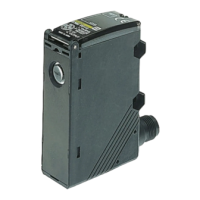
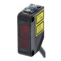
E3JK
Operation
Adjustment
Precautions
Design
Power Reset Time
The Sensor is ready to detect an object within 200 ms after it
is turned ON. If Sensor and load are connected to separate
power supplies, ensure to turn ON the Sensor first.
Wiring Considerations
Connection/Wiring
If the DC transistor output type is used, the sum of load cur-
rents of L-ON output (NO) and D-ON output (NC) should be
within 100 mA. If the sum of load currents exceeds 100 mA,
the load short-circuit protection may be activated. (The load
short-circuit protection is reset by turning OFF the power of
the photoelectric sensor.)
Miscellaneous
Ambient Conditions (Installation Area)
The E3JK will malfunction if installed in the following places.
• Places where the E3JK is exposed to a dusty environment.
• Places where corrosive gases are produced.
• Places where the E3JK is directly exposed to water, oil, or
chemicals.
Item
Through-beam Retroreflective Models Diffuse-reflective
Model
E3JK
Swing the receiver and emitter ver-
tically and/or horizontally and set
the adjuster in the center of the
range where the indicator of the re-
ceiver turns ON.
Like the through-beam model, ad-
just the reflector and emitter/re-
ceiver. Since the directional angle
of the emitter/receiver is 1 to 5°, ad-
just the emitter/receiver especially
carefully.
(1) If you have a sensing object as shown in the figure, turn the sensitivity
adjuster clockwise (increase the sensitivity) until the indicator is turned
ON, and define this adjuster position as (A).
(2) Remove the sensing object, turn the sensitivity adjuster clockwise until
the indicator is turned ON by a background object, and define this posi-
tion as (B).
(3) Turn the sensitivity adjuster counterclockwise (decrease the sensitivity)
from (B) until the indicator is turned OFF, and define this position as (C).
(4) The position in the middle of (A) and (C) is the optimum position. If the
indicator is not turned ON by the background object at the maximum
sensitivity, set the adjuster in the middle of (A) and maximum sensitivity.
The sensitivity adjuster may be damaged if an excessive force is applied.
Correct Use
With sensing object Without sensing object
Operation
Sensitivity
MIN MAX
Reset
Operation
(C)
(C)
(A)
(A)
Setting
(B)
Background
object
Sensitivity
MIN MAX
(A)
Sensitivity
MIN MAX
E3JK
Emitter
Receiver
Emitter
Receiver