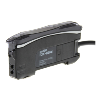
E3X-HD
10
Mounting the Fiber Amplifier Units
Mounting on DIN Track
Mounting Amplifier Units in Group
(Connector Type Models)
• Under environments such as vibration, use an end plates even with a single
Fiber Amplifier Unit.
• The maximum numbers of connectable Amplifier Units are given in the
following table.
• The mutual interference prevention function cannot be used if the detection
mode is set to super-high-speed mode (SHS).
• If Units are to be connected, the allowable ambient temperature will change
with the number of Units that are connected. Check the Ratings and
Specifications.
• Always turn OFF the power before connecting or disconnecting Units.
Mounting Fiber Units
Use Fiber Cutter
Cut a thin fiber as follows.
For standard fibers, insert to the desired cutting position and cut.
Mount Fiber Unit
1. Let the hook on the Amplifier
Unit’s Fiber Unit connection side
catch the track and push the unit
until it clicks.
Removing from DIN Track
1. Push the unit in the direction 1.
2. Lift it up in the direction 2.
Note: Refer to I/O Circuit Diagrams
or check the side of the unit for
wire color and role indications.
1. Mount the Fiber Amplifier units one
at a time onto the DIN track and
push them until they click.
2. Slide the Fiber Amplifier units in the
direction 2.
3. Use End Plates (PFP-M:
separately sold) at the both ends of
the grouped Fiber Amplifier units to
prevent them from separating due
to vibration or other cause.
4. Tighten the screw on the End
Plates using a driver.
Maximum
number of
interconnected
Maximum
number of
mutual
interference
prevention
E3X-HD series standard models
(E3X-HD11/HD41/HD6/HD8)
16 10
E3X-HD0
With E3X-ECT 30 10
With E3X-CRT 16 10
1.
The fiber is
shipped loosely
tightened as
shown in the
figure at the right.
2.
Adjust the fiber
to the desired
length and fully
tighten.
3.
Insert the Fiber
Unit into E39-F4
and cut it.
4.
Finished state.
(Correctly cut
end)
1. Open the protective cover.
2. Raise the lock lever.
3. Insert the Fiber Unit in the fiber
unit hole to the bottom.
4. Return the lock lever to the
original position and fix the
Fiber Unit.
• When mounting a coaxial reflective
Fiber Unit, insert the single-core
Fiber Unit to the upper hole (Emitter
side) and the multi-core Fiber Unit to
the lower hole (Receiver side).
The cables for the Single-core Fiber
Units (Emitters) have identification
marks. Refer to the dimensions
diagrams for details.
• When removing the Fiber Unit, follow the above steps in reverse order.
To maintain the characteristics of the Fiber Unit, make sure the lock is
released before removing the Fiber Unit.
Erstellt am 28.09.2020 um 20:20 Uhr | Alle Angaben ohne Gewähr, Irrtümer und Änderungen vorbehalten! Seite 11 von 14

 Loading...