Do you have a question about the Omron E3X-DA-N and is the answer not in the manual?
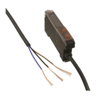
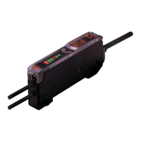
Lists different amplifier types by appearance and output.
Details the programmer unit, its power supply, and accessories.
Describes connector cables, their appearance, length, and applicable amplifiers.
Lists mounting brackets and end plates for the amplifiers.
Introduces the use of E32-series fiber-optic cables with the E3X-DA-N.
Details electrical, environmental, and functional specifications for amplifiers.
Explains the three display modes: Digital Incident Level, Percent, and Analog.
Covers functions like Sensing, Timer, Flashing, and Display Hold.
Illustrates NPN and PNP output circuits with timing charts and transistor states.
Describes the procedure for setting maximum sensitivity for optimal detection.
Details the teaching method without an object for setting detection thresholds.
Explains teaching with and without an object to set detection thresholds.
Describes precise positioning setup using teach functions.
Shows typical operating ranges for through-beam fiber types.
Illustrates operating ranges for various reflective fiber types.
Plots excess gain ratio against sensing distance for different fibers.
Relates sensing distance to operating range for specific fibers.
Shows differential travel based on sensing distance for reflective fibers.
Displays repeat accuracy relative to sensing distance for reflective fibers.
Graphs analog output voltage against distance for through-beam fibers.
Shows operating ranges for mark detection sensors with through-beam fibers.
Illustrates operating ranges for convergent reflective fiber types.
Provides detailed dimensional drawings for E3X-CN connector amplifiers.
Shows dimensions when a master connector is attached.
Shows dimensions when a slave connector is attached.
Details dimensions for amplifiers with M8 connectors.
Provides dimensional drawings for prewired amplifiers.
Shows dimensions and specifications for E3X-CN master connectors.
Shows dimensions and specifications for E3X-CN slave connectors.
Details the dimensions of the remote control programmer and its head.
Provides dimensions for the E39-L143 mounting bracket.
Shows dimensions for the PFP-M end plate.
Illustrates wiring connections, including with a process meter.
Describes how to connect multiple amplifier units on a DIN rail.
Explains how to detach amplifier units from DIN rail or bracket.
Details the process for disconnecting joined amplifier units.
Guides on positioning the communication head relative to amplifiers.
Lists critical warnings to prevent unit damage.
Advises on power reset time, power supply, and grounding.
Provides guidance on cable extension, force limits, and noise.
Covers interference, EEPROM errors, and hysteresis settings.
Includes notes on typical values and general handling.
Details tightening torque for various sensing heads.
Explains how to connect and disconnect fiber optic cables to the amplifier.
Describes how to insert master/slave connectors into amplifier units.
Explains the procedure to detach connectors from amplifier units.
Details the use of end plates to secure amplifier units.
Lists sensing distances for various through-beam fiber models.
Details sensing distances for specialized through-beam fiber types.
Lists sensing distances for specialized diffuse fiber models.
Covers sensing distances and features for retroreflective fiber types.
| Output Current | 100 mA max. |
|---|---|
| Degree of Protection | IP67 |
| Type | Fiber Amplifier |
| Output Type | NPN |
| Supply Voltage | 12 to 24 VDC |
| Current Consumption | 40 mA max. |
| Sensing Distance | Varies with fiber unit |
| Residual Voltage | 1 V max. |
| Light Source | Red LED |
| Indicator | LED |
| Protection Circuit | Reverse polarity protection |
| Operating Temperature | -25 to 55°C |
| Storage Temperature | -40 to 70 °C |
| Ambient Humidity | 35 to 85% RH |
| Vibration Resistance | 10 to 55 Hz, 1.5 mm |
| Shock Resistance | 500 m/s² |
| Housing Material | ABS |
| Connection | 2 m cable |