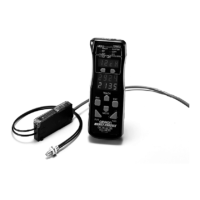
E3X-DA-N
E3X-DA-N
21
Precautions
J AVOID DAMAGE TO THE E3X-DA-N
• Voltage must not exceed the rated voltage of the E3X-DA-N.
• When supplying power to the E3X-DA-N, make sure that the
polarity of the power is correct.
• Do not short-circuit the load connected to the E3X-DA-N.
• Do not impose 100 VAC or more on models that operate
with DC.
• Do not use the E3X-DA-N in environments where flammable
or explosive gas exists.
• Do not disassemble, repair or modify the E3X-DA-N.
• The E3X-DA-N has an enclosure rating of IP50; do not im-
merse in water.
• Load must be connected to the E3X-DA-N.
J INSTALLATION
Power Reset Time
• The E3X-DA-N is ready to sense objects 100 ms after the
unit is turned on.
• If power is supplied to the E3X-DA-N and the load
independently, make sure to turn ON the E3X-DA-N first.
• When the E3X-DA-N is turned ON or OFF, the operation
indicator will be illuminated for an instant, but no control out-
put will be turned ON.
Power Supply
• Do not connect the E3X-DA-N to a full-wave or half-wave
rectified power supply.
• When a standard switching power supply is used, the frame
ground (FG) and the ground (G) terminal must be grounded.
Otherwise, the E3X-DA-N may experience noise problem.
J WIRING
Cable
• The cable can be extended up to 100 m provided the wire
thickness is at least 0.3 mm
2
.
• Do not pull cables with pulling force exceeding 50N.
Avoid Damage or Malfunction Due to Induction Noise
• Never run the E3X-DA-N cables in the same conduit with
power lines or high tension cables.
J ADJUSTMENT
Mutual Interference Protection Function
There may be some instability in the digital display values due to
light from other sensors. If this occurs, increase the sensitivity
(i.e., decrease the threshold) to perform stable detection.
EEPROM Writing Error
If the data is not written to the EEPROM correctly due to a power
failure during teaching or static-electric noise, repeat the whole
teaching procedure.
Optical Communications
Several Amplifier Units can be slid together and used in groups.
Do not, however, slide the Amplifier Units or attempt to remove
any of the Amplifier Units during operation.
Hysteresis Adjustment
The hysteresis setting can be adjusted using the Remote Control
Programmer. Do not, however, set the hysteresis to a value
lower than the factory setting. Using a setting less than the
factory setting may result in incorrect operation.
J OTHERS
Typical Values
Minimum sensing object and characteristic data values are
typical values checked on actual products selected at random.
None of these values represent a guaranteed rating or
performance value.

 Loading...