EasyManua.ls Logo

Omron E3X-DA-N series User Manual

Omron E3X-DA-N series
37 pages
To Next Page IconTo Next Page
Page #1 background imageLoading...
Page #1 background image
Digital Fiber Amplifier
E3X-DA-N
The Ultimate Fiber Amplifier for
Maximum Ease of Use and High
Performance
Be sure to read Safety Precautions
on page 23.
UL991*
* UL certification including UL 991 testing and evaluation Applicable standards: UL 3121-1
Additional application testing and evaluations standards: UL 991 and SEMI S2-0200S
Features
Models with New Connector System
Reduces Wiring, Saves Space, and Makes
Maintenance Easier
In Amplifiers with wire-saving connectors, the power supply is
distributed to 1-conductor slave connectors through a 3-
conductor master connector. This design has three major
advantages.
1. Wiring time is significantly reduced.
2. Relay connectors are unnecessary, so wiring takes up less
space and costs are reduced.
3. Storage and maintenance are simpler because it isn't
necessary to distinguish between master connector and
slave connectors on the Amplifier.
Super Digital Display with Auto Power
Control (APC) Circuit
The passage of time causes the intensity of the Sensor's light-
emitting LED elements to deteriorate, which may make stable
detection impossible.
The E3X-DA-N is the first series of Fiber Sensors to use an
Auto Power Control (APC) circuit. This achieves strict
detection by eliminating fluctuation in the digital value and is
ideal for subtle detection such as stable detection of liquid-
crystal glass.
First in the Industry Patent Pending
Master connector
Simplified Connector Design
Slave connector
Up to 16 Amplifiers can
be connected.
Power
supply pin
Optical
communi-
cations
First in the Industry
Incident level
Time
Threshold
3000
Unstable detection
Incident level
Time
3000
Stable detection
Previous Digital
Fiber Amplifiers
E3X-DA-N Series
Threshold
http://www.ia.omron.com/
1
(c)Copyright OMRON Corporation 2007 All Rights Reserved.

Table of Contents

Question and Answer IconNeed help?

Do you have a question about the Omron E3X-DA-N series and is the answer not in the manual?

Omron E3X-DA-N series Specifications

General IconGeneral
ModelE3X-DA-N series
CategoryAmplifier
Response Time1 ms max.
Power Supply Voltage12-24 VDC ±10%
Current Consumption40 mA max.
Output TypeNPN/PNP open collector
Operating Temperature-25 to 55°C (with no icing or condensation)
Protection CircuitReverse polarity protection
Ambient Humidity35 to 85% RH (with no condensation)
Light SourceRed LED

Summary

Features

Models with New Connector System

Wire-saving connector design for easier wiring and maintenance.

Super Digital Display with APC Circuit

APC circuit for stable detection and its benefits.

Product Enhancements and Convenience

Power Consumption Reduction

Details on power reduction features, including Eco-mode.

Mobile Console for Remote Operation

Cellular-phone-sized mobile consoles for remote setup and adjustment.

Ordering Information

Pre-wired Amplifier Models

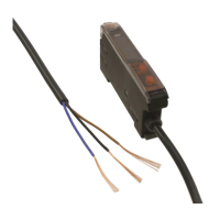
Catalog of pre-wired amplifier models with specifications.

Amplifiers with Standard Connectors

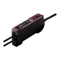
Catalog of amplifiers with standard connectors, detailing types.

Connectors and Configuration

Amplifier Connector Types

Details on separately ordered master and slave connectors.

Combining Amplifiers and Connectors

Guidance on combining amplifier models with applicable connectors.

M8 Sensor I/O Connectors

Specifications for separately ordered M8 sensor I/O connectors.

Accessories and Mobile Console

Mobile Console Components

Overview of mobile console models, heads, and cables.

Mounting Brackets and Stickers

Information on mounting brackets and operating instruction stickers.

Ratings and Specifications (Pre-wired)

Output, Response, and Functions

Details on output types, response times, and amplifier functions.

Indicators and Settings

Description of indicators and sensitivity/timer settings.

Ratings and Specifications (Connected)

Environmental and Electrical Specs

Details on operating temperature, humidity, and protection ratings.

Connector and Console Specs

Specifications for connectors and the mobile console.

Differential Models and Fiber Unit Data

Fiber Unit Characteristics

Sensing distance and object data for fiber units.

E3X-DA-N vs. Differential Models

Comparison of features between E3X-DA-N and differential models.

Technical Reference (Twin-output)

Normal Operation Output Patterns

Illustrates the four possible output patterns for twin-output models.

Area Sensing Output Patterns

Describes area sensing functionality and its output patterns.

I/O Circuit Diagrams

NPN Output Circuits

Circuit diagrams and timing charts for NPN output models.

M8 Connector Wiring

Wiring and pin details for M8 sensor connectors.

PNP Output Circuit Diagrams

PNP Output Configurations

Circuit diagrams and timing charts for PNP output models.

Connection and Nomenclature

Connection with K3NX-VD2

Wiring example for connecting E3X-DA-N with a K3NX-VD2.

Amplifier Control Nomenclature

Labeling of controls and indicators on the amplifiers.

Amplifier Adjustments

Display Modes and Zero-reset

Changing display and performing zero-reset in RUN mode.

Initial Reset and Manual Tuning

Procedures for initial reset and fine sensitivity adjustment.

Setting Functions in SET Mode

All Models: Sensing and Timer Settings

Configuration of sensing function, timer, flashing, and hold settings.

All Models: Monitor and Display Settings

Settings for monitor focus and display orientation.

Setting Functions for Twin-output Models

Twin-output: Operating Mode and Sensing

Setting operating modes and sensing functions for twin-output models.

Twin-output: Area Sensing Setup

Details on setting up and using the area sensing feature.

Teaching Procedures

Maximum Sensitivity Teaching

Steps for maximum sensitivity using two-point or one-point teaching.

Pin-point Teaching for Positioning

Procedure for precise positioning using pin-point teaching.

Safety Precautions

Amplifier Mounting and Fiber Handling

Guidelines for mounting amplifiers and connecting/disconnecting fiber optics.

Operational Safety and Interference

Important notes on operation, console mounting, and interference.

Connector and Amplifier Handling

Connector Mounting and Removal

Instructions for mounting, removing, and handling amplifier connectors.

End Plate Mounting

Guidance on mounting the End Plate for amplifier stability.

Accessories

Operating Instructions Sticker

Information on applying the operating instructions sticker.

Dimensions: Pre-wired and Water-resistant

Pre-wired Amplifier Dimensions

Detailed dimensions for pre-wired amplifiers with mounting brackets.

Water-resistant Model Dimensions

Dimensions for water-resistant amplifier models with mounting brackets.

Dimensions: Twin-output and Standard Connectors

Twin-output Amplifier Dimensions

Dimensions for twin-output amplifiers with mounting brackets.

Standard Connector Amplifier Dimensions

Dimensions for amplifiers with standard connectors, showing connections.

Dimensions: M8 and Twin-output Connectors

M8 Water-resistant Amplifier Dimensions

Dimensions for M8 water-resistant amplifiers with mounting brackets.

Twin-output Connector Amplifier Dimensions

Dimensions for twin-output amplifiers with standard connectors.

Connectors and Mobile Console Details

Master/Slave Connector Specs

Details on master and slave connector types and specifications.

Mobile Console and Accessories Specs

Specifications for the mobile console, head, and mounting brackets.

General Precautions

Wiring and Power Supply Safety

Essential safety precautions for wiring and power supply connections.

Operating Environment Safety

Guidelines for safe operation in various environmental conditions.

Correct Use and Interference Prevention

Avoiding Mutual Interference

Measures to prevent mutual interference between sensors.

Sensor Mounting and Alignment

Guidance on mounting, alignment, and sensitivity adjustments.

Noise Countermeasures and Cable Handling

Noise Intrusion and Mitigation

Methods to mitigate noise from common, radiant, and power line sources.

Cable Management and Separation

Precautions for cable tensile strength, bending, and separation.

Power Supply and Cable Testing

Power Supply Connection Example

Example connection for DC three-wire NPN output sensors.

Cable Bending Test Results

Results of cable bending tests comparing standard and robot cables.

Fiber Unit and Optical Axis Adjustment

Attaching and Removing Fibers

Procedure for securing and removing fiber units using the locking mechanism.

Optical Axis Alignment Guide

Methods for adjusting the optical axis for optimal sensor performance.

Environmental Use and Maintenance

Operating Environment Limitations

Restrictions for using sensors in hazardous or specific environments.

Sensor Maintenance and Inspection

Key checks for troubleshooting and maintaining sensor operation.

Warranty, Liability, and Usage Considerations

Warranty and Limitations of Liability

OMRON's warranty terms and limitations of liability for product use.

Application Considerations and Disclaimers

Guidance on product suitability, application examples, and catalog disclaimers.

Related product manuals