Do you have a question about the Omron E3X-NA11 and is the answer not in the manual?
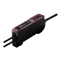
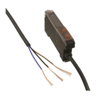
Details amplifier units with attached cables, covering type, part numbers, control output, and appearance.
Lists connector-ready amplifier units with part numbers, applicable connectors, control output, and appearance.
Details amplifier unit connectors, including appearance, cable length, number of conductors, and part numbers.
Guidance on combining amplifier units and connectors, with examples for ordering.
Details sensor I/O connectors, including size, cable specifications, appearance, cable type, and part numbers.
Lists separate accessories such as mounting brackets, end plates, and fiber-optic cables.
Comprehensive specifications for amplifier units, including output type, light source, supply voltage, and response time.
Specifications for amplifier unit connectors, detailing rated current, voltage, contact resistance, and material.
Illustrates and labels the components and indicators of the amplifier units.
Explains the function of the LED bar display for incident level indicators and operation status.
Diagrams and explanations of NPN and PNP output circuits, including timing charts and transistor states.
Details the terminal numbers, conductor colors, and applications for sensor I/O connectors.
Graphical representation of parallel operating ranges for various fiber units at max sensitivity.
Graphical data showing operating ranges for different fiber units with standard sensing targets.
Dimensional drawings for amplifier units with cables and mounting brackets.
Dimensional drawings for water-resistant amplifier units with cables and mounting brackets.
Dimensional views of wire-saving amplifiers connected to master connectors.
Dimensional views of wire-saving amplifiers connected to slave connectors.
Dimensional details and notes for master connectors (E3X-CN11).
Dimensional details and notes for slave connectors (E3X-CN12).
Dimensional drawings and specifications for straight sensor I/O connectors.
Dimensional drawings and specifications for L-shaped sensor I/O connectors.
Dimensional details for mounting brackets E39-L143.
Dimensional details for mounting brackets E39-L148.
Dimensional details for the end plate (PFP-M).
Safety precautions related to power supply voltage, load short-circuits, polarity, and no-load operation.
Precautions for turning power ON/OFF, power supply type, and communications hole usage.
Guidelines for wiring amplifier units, including cable extension, separation from power lines, and power supply types.
Procedure for joining multiple amplifier units together for mounting.
Procedure for separating amplifier units that have been joined together.
Instructions for mounting amplifier units onto brackets or DIN rails.
Steps for removing amplifier units from their mounting.
Considerations for operating environment, like dust accumulation on optical holes.
Note on how ratings and specifications are derived from random samples.
Instruction to ensure the protective cover is mounted before use.
Specifies the recommended tightening force for fiber unit screws.
Instructions and procedures for cutting fiber optic cables using a fiber cutter.
Step-by-step guide for connecting and disconnecting fiber units to the amplifier.
Procedure for mounting amplifier units with master or slave connectors attached.
Guidance on using the sleeve bender to maintain optimal bending radius for fiber tubes.
Precautions for using E39-R3 reflectors, including surface cleaning and environmental limitations.
Instructions for using the E39-R3 reflector, focusing on surface cleaning and handling.
Procedure for inserting fiber into protective spiral tubes and securing them.
Table detailing sensing distances and specifications for through-beam fiber units.
Sensing distances and specifications for reflective sensors for long-distance applications.
Specifications for reflective sensors with 3-mm diameter, small diameter, and various applications.
Specifications for general-purpose reflective sensors with M3 and M6 screw types.
Specifications for reflective sensors with M3 screw, small diameter, and specific applications.
Specifications for thin fiber reflective sensors, including sleeve and diameter options.
Details on reflective sensors with 2.5-mm dia. fiber and sleeve, for various applications.
Specifications for reflective sensors with 1.2-mm dia. fiber and sleeve, including application details.
Specifications for reflective sensors with 0.8-mm dia. fiber for detecting minute targets.
Specifications for reflective sensors with 0.5-mm dia. fiber for detecting minute targets.
Details on amplifier units, including output types, part numbers, light source, and voltage specifications.
Identification and labeling of amplifier unit components and indicators.
Diagrams illustrating NPN and PNP output circuits for the amplifier.
Explanation of the Light-ON and Dark-ON operation modes.
Overview of sensitivity setting methods: maximum, slight differences, and without objects.
Methods for fine-tuning sensitivity on production lines and ideal operation in changing environments.
Detailed procedure for manual fine sensitivity adjustment.
Explanation of the auto-tuning function for automatic sensitivity compensation.
Procedure for setting the amplifier to maximum sensitivity.
Step-by-step guide for performing two-point sensitivity teaching.
Procedure for one-point teach mode for diffuse (Light-ON) fiber units.
Procedure for one-point teach mode for through-beam (Dark-ON) fiber units.
Detailed steps for manual tuning, adjusting sensitivity via UP/DOWN selector.
Procedure for initiating auto-tuning for automatic sensitivity compensation.
Guidelines for maximum sensitivity setting with through-beam and diffuse fiber units.
Procedure for 2-point teach mode for detecting surface irregularities or irregular reflections.
Explanation of incident level indicators in RUN/ADJ mode and manual-tuning levels.
Procedure for one-point teach mode for diffuse (Light-ON) units.
Procedure for one-point teach mode for through-beam (Dark-ON) units.
Procedure for setting the initial threshold using one-point teaching and auto-tuning.
Explanation of automatic threshold compensation and its timing.
Dimensional drawings and specifications for the E3X-NH amplifier unit.
Instructions for cutting fiber optic cables and marking for insertion.
Steps for connecting and disconnecting fiber units using the lock button.
Guidelines for connecting fiber units, including force limits and bending radius.
Guidance on using the sleeve bender for optimal fiber bending radius.
Precautions for using E39-R3 reflectors, including cleaning and environmental restrictions.
Procedure for connecting fibers using the E39-F10 Fiber Connector.
Instructions for inserting fiber into protective spiral tubes and securing them.
Instructions for mounting amplifier units onto brackets or DIN rails.
Steps for removing amplifier units from their mounting.
General safety warning regarding the E3X-NH as a non-safety component.
Precautions to prevent damage to the sensor, covering voltage, polarity, and load.
Precautions for using E39-R3 reflectors regarding surface cleaning and exposure.
Specific precautions for E39-R3 reflector use, including cleaning and chemical exposure.
Guidance on performing two-point teaching to prevent mutual interference.
Note on potential EEPROM writing errors and the need to re-teach.
Disclaimer that typical examples for minute object detection are for reference only.
Warning about potential pulse signals when power is turned off.
Precautions for power supply grounding and voltage requirements.
Instructions to avoid wiring amplifier and power lines in the same conduit.
| Model | E3X-NA11 |
|---|---|
| Category | Amplifier |
| Output Type | NPN |
| IP Rating | IP67 |
| Housing Material | ABS |
| Supply Voltage | 12 to 24 VDC ±10%, ripple (p-p): 10% max. |
| Response Time | 1 ms |
| Operating Temperature | -25 to 55°C (with no icing or condensation) |
| Light Source | Red LED |
| Protection Circuit | Reverse polarity protection, short-circuit protection |
| Ambient Humidity | 35 to 85% RH (with no condensation) |
| Output Configuration | NPN |
| Connection Method | Pre-wired (2 m) |