5
E3X-NAE3X-NA
Operation
■
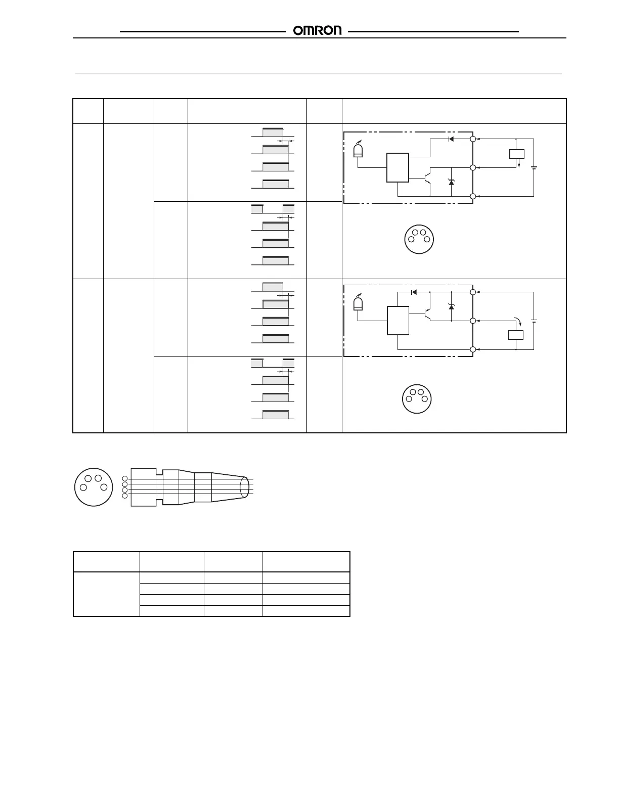
Output Circuits
Output Model Mode
selector
Timing chart State of
output
transistor
Output circuit
NPN E3X-NA11
E3X-NA6
E3X-NAG11
E3X-NA11F
E3X-NA11V
E3X-NA14V
LIGHT
ON
(L/ON)
Light ON
DARK
ON
(D/ON)
Dark ON
PNP E3X-NA41
E3X-NA8
E3X-NAG41
E3X-NA41F
E3X-NA41V
E3X-NA44V
LIGHT
ON
(L/ON)
Light ON
DARK
ON
(D/ON)
Dark ON
F
F
Incident li
h
No incident li
h
Operation indicator
(orange)
Output
transistor
Load (relay) Operat
R
l
Between brown and black
Operation
indicator
(orange)
Photo-
electric
Sensor
main
circuit
Brown
Black
Control output
Blue
1
4
3
Load
12 to
24 VDC
1
2
4
3
Photo-
electric
Sensor
main
circuit
M8 Connector Pin Arrangement
Note: Pin 2 is not used.
F
F
Incident li
h
No incident li
h
Operation indicator
(orange)
Output
transistor
Load (relay) Operat
R
l
Between brown and black
F
F
Incident li
h
No incident li
h
Operation indicator
(orange)
Output
transistor
Load (relay) Operat
R
l
Between brown and black
Operation
indicator
(orange)
Brown
Black
Control output
12 to
24 VDC
Blue
1
4
3
Load
1
2
4
3
Photo-
electric
Sensor
main
circuit
M8 Connector Pin Arrangement
Note: Pin 2 is not used.
F
F
Incident li
h
No incident li
h
Operation indicator
(orange)
Output
transistor
Load (relay) Operat
R
l
Between brown and blac
■
Connectors (Sensor I/O Connectors)
Note: Pin 2 is not used.
Classification Color of cable
conductors
Connection
pin number
Application
DC Brown 1 Power supply (+V)
White 2 ---
Blue 3 Power supply (0 V)
Black 4 Output
2
4
1
3
1
2
3
4
Color of cable
conductors
Brown
White
Blue
Black
XS3F-M421-402-A, XS3F-M422-402-A
XS3F-M421-405-A, XS3F-M422-405-A
Terminal number

 Loading...