E3X-DA-N
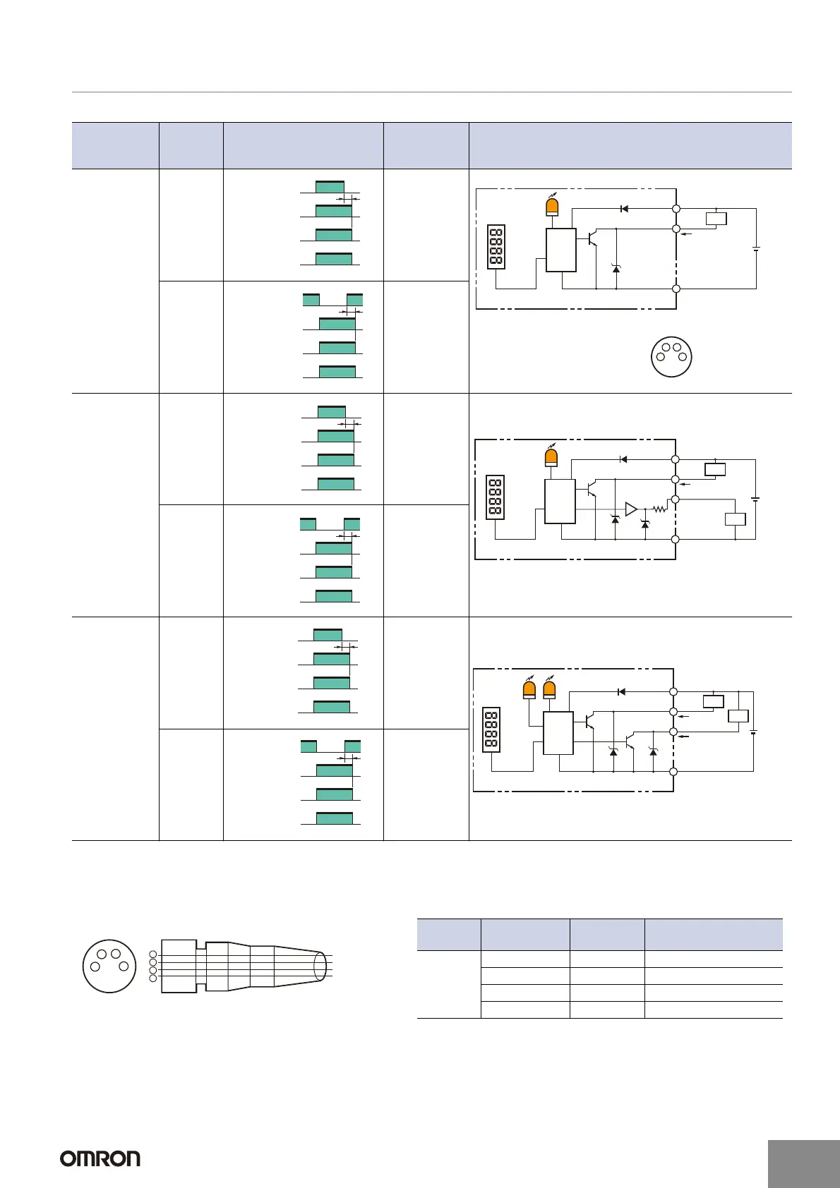
I/O Circuit Diagrams
NPN Output
Note: With E3X-DA@TW models, only channel 1 is output when set for area sensing operation.
LIGHT ON: ON when the incident level is between the thresholds for channels 1 and 2.
DARK ON: OFF when the incident level is between the thresholds for channels 1 and 2. (Channel 2 is always OFF.)
Sensor I/O Connectors for Models with M8 Connectors
Model
Opera-
tion
mode
Timing charts
Mode selec-
tor switch
Output circuit
E3X-DA11-N
E3X-DAB11-N
E3X-DAG11-N
E3X-DAH11-N
E3X-DA11V
E3X-DA6
E3X-DAB6
E3X-DAG6
E3X-DAH6
E3X-DA14V
Light-ON
L-ON
(LIGHT ON)
Dark-ON
D-ON
(DARK ON)
E3X-DA21-N
E3X-DA7
Light-ON
L-ON
(LIGHT ON)
Dark-ON
D-ON
(DARK ON)
E3X-DA11TW
E3X-DA6TW
Light-ON
L-ON
(LIGHT ON)
Dark-ON
D-ON
(DARK ON)
Incident light
No incident light
ON
OFF
ON
OFF
Operate
Reset
Operation
indicator
(orange)
(Between brown and black)
Output
transistor
Load
(e.g., relay)
T
Load
Operation indicator (orange)
Brown
1
3
4
Black
Blue
Control output
12 to
24 VDC
Display
• Connector Pin Arrangement
(M-8 Connector only)
Note: Pin 2 is not used.
1
2
4
3
Photo-
electric
Sensor
main
circuit
T
Incident light
No incident light
ON
OFF
ON
OFF
Operate
Reset
(Between brown and black)
Operation
indicator
(orange)
Output
transistor
Load
(e.g., relay)
T
Incident light
No incident light
ON
OFF
ON
OFF
Operate
Reset
(Between brown and black)
Operation
indicator
(orange)
Output
transistor
Load
(e.g., relay)
Orange
*
* Load resistance: 10 kΩ min.
47 Ω
Load
Operation indicator (orange)
Brown
Black
Blue
Control output
12 to
24 VDC
Display
Photo-
electric
Sensor
main
circuit
Load
Monitor
output
1 to 5 V
T
Incident light
No incident light
ON
OFF
ON
OFF
Operate
Reset
(Between brown and black)
Operation
indicator
(orange)
Output
transistor
Load
(e.g., relay)
T
CH1/
CH2
Incident light
No incident light
ON
OFF
ON
OFF
Operate
Reset
(Between brown and black)
Operation
indicator
(orange)
Output
transistor
Load
(e.g., relay)
Orange
Load
Operation indicator (orange)
Brown
Black
Blue
Control output 1
12 to
24 VDC
Display
Photo-
electric
Sensor
main
circuit
Load
Operation
indicator
(orange)
Control output 2
T
CH1/
CH2
Incident light
No incident light
ON
OFF
ON
OFF
Operate
Reset
(Between brown and black)
Operation
indicator
(orange)
Output
transistor
Load
(e.g., relay)
2
4
1
3
1
2
3
4
Brown
White
Blue
Black
Wire colors
XS3F-M421-402-A
XS3F-M421-405-A
XS3F-M422-402-A
XS3F-M422-405-A
Note: Pin 2 is not used.
Classifi-
cation
Wire colors
Connection
pin No.
Application
DC
Brown 1 Power supply (+V)
White 2 ---
Blue 3 Power supply (0 V)
Black 4 Output
http://www.ia.omron.com/
16
(c)Copyright OMRON Corporation 2007 All Rights Reserved.
 Loading...