E3X-DA-NE3X-DA-N
12
J ZERO RESET FUNCTION
When activated, this function sets the incident level digital display
to zero. This enables operators to easily monitor the difference
between the maximum and the minimum incident levels.
1. Set the “SET ADJ RUN” switch to “RUN” position.
2. Press the “TEACH” button for 1 second. A zero should ap-
pear in the display.
3. Press the “TEACH” and “MODE” buttons simultaneously for
3 seconds to return to the initial incident level display.
Hold down both for 3 s
J INITIAL RESET
This function enables users to cancel program input and reset
the amplifier back to the default (factory) setting
1. Set the “SET ADJ RUN” switch to “SET” position.
2. Press the “TEACH” and “MODE” buttons simultaneously for
5 seconds until “NO ?” is displayed.
Hold down both for 5 s
To cancel “Initial Reset” function, simply press the “MODE”
button.
Press to cancel.
To implement the “Initial Reset” function, first press the
“TEACH” button until “YES?” appears in the display.
Press the “MODE” button to execute the “Initial Reset”
function.
Press to execute initial reset.
3. Set the “SET ADJ RUN” switch to “RUN” position to imple-
ment settings from the teach function.
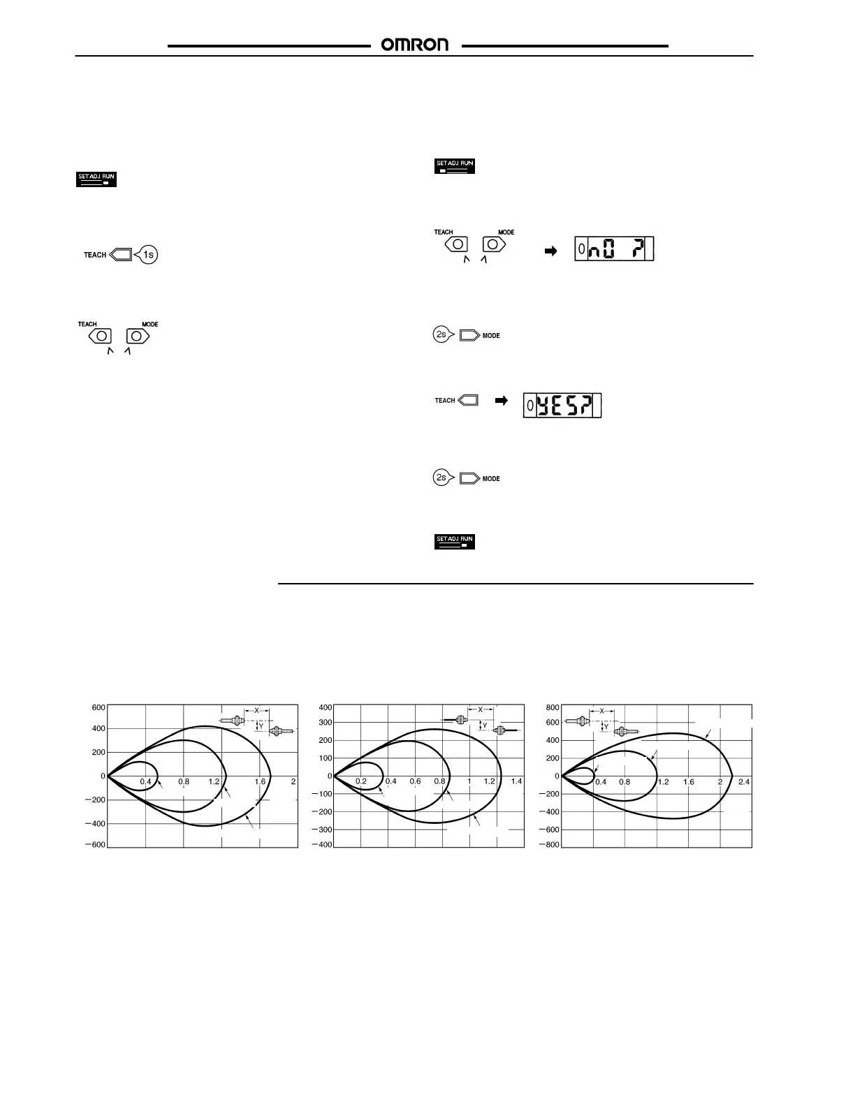
Engineering Data
J PARALLEL OPERATING RANGE (TYPICAL)
At max. sensitivity. (Use for optical axis adjustment at installation.)
E32-TC200
(Through-beam)
E32-T11R
(Through-beam)
E32-T11
(Through-beam)
Distance Y (mm)
Standard
Long distance
Distance Y (mm)
High speed
Standard
Long distance
Distance Y (mm)
High speed
Standard
Long distance
Distance X (m)Distance X (m)Distance X (m)
High speed