EasyManuals Logo

Omron E3Z series Network Connection Guide

Omron E3Z series
46 pages
To Next Page IconTo Next Page
To Previous Page IconTo Previous Page
Page #17 background imageLoading...
Page #17 background image
7
IO-Link Connection Procedure
14
4
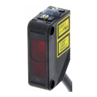
Set Rotary switches and DIP
switch as follows:
Rotary switches
x10: 0
x1: 1
DIP switch
4(ADR+100): OFF
*The node address is set to 1.
Rotary switches DIP switch
5
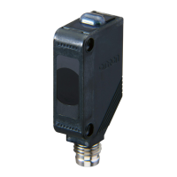
Connect an Ethernet cable to
Communications connector (IN)
on EtherCAT Coupler Unit.
6
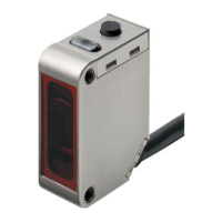
Connect Unit power supply to
Unit power supply terminals on
EtherCAT Coupler Unit.
Connect I/O power supply to I/O
power supply terminals.
*For details on power supply
specifications of NX-series
Slave Terminals, refer to
Section 5. Designing the Power
Supply System of the
NX-series EtherCAT(R)
Coupler Unit Users Manual
(Cat. No. W519).
Ethernet cable
Unit power supply
I/O power supply
Communications
connector (IN)
Unit power supply terminals
I/O power supply terminals

Other manuals for Omron E3Z series

Questions and Answers:

Question and Answer IconNeed help?

Do you have a question about the Omron E3Z series and is the answer not in the manual?

Omron E3Z series Specifications

General IconGeneral
Protection RatingIP67
Response Time1 ms or less
Accessory TypePhotoelectric Sensor
Connection TypePre-wired, Connector
Sensing MethodThrough-beam, Retro-reflective, Diffuse-reflective
Light SourceInfrared LED, Red LED
Power Supply Voltage12 to 24 VDC
Output TypeNPN, PNP
Operating Temperature-25 to 55°C
Sensing Distancevaries by model (up to 30m for Through-beam)

Related product manuals