6 Photoelectric Sensor
I/O Circuit Diagrams
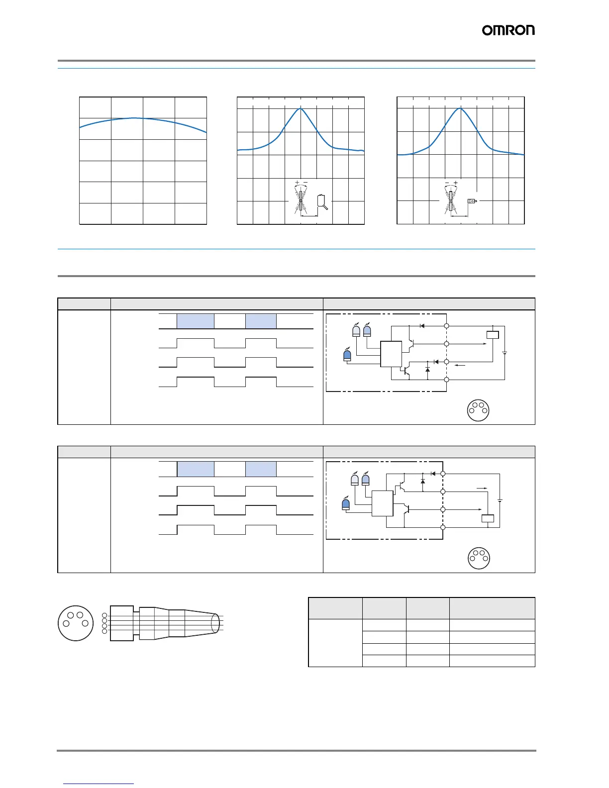
NPN Output
PNP Output
Plugs (Sensor I/O Connectors)
M8 4-pin Connectors
Note: The above M8 Connectors made by OMRON are IP67.
Do not use them in an enviornment where IP69K is required.
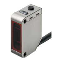
Excess Gain vs. Distance
E3ZM-V@@
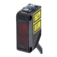
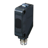
Angle vs. Incident Characteristics
E3ZM-V@@ E3ZM-V@@
Model Timing charts Output circut
E3ZM-V61
E3ZM-V66
Model Timing charts Output circut
E3ZM-V81
E3ZM-V86
10 11 12 13 14
100
80
60
40
20
Incident light (%)
Distance (mm)
0
120
Incident light (%)
−20 −15 −10 −5 0 5 10 15 20
Angle (°)
100
80
60
40
20
0
Te aching ON for white and OFF for black at 12 mm
12 mm
100
80
60
40
20
0
Te aching ON for white and OFF for black at 12 mm
12 mm
Incident light (%)
−20 −15 −10 −5 0 5 10 15 20
Angle (°)
Color taught
2nd
Between brown (1)
and black (4) leads
Color taught
1st
Color taught
2nd
Color taught
1st
ON
OFF
ON
OFF
Operate
Reset
Sensing object
Operation
indicator
(yellow)
Output
transistor
Load
(e.g., relay)
Control output
Remote control input
1
2
4
3
10 to
30 VDC
Brown
Black
Blue
Pink
Operation
indicator
(yellow)
Stability
indicator
(green)
Te aching
indicator
(red)
Photo-
electric
Sensor
Main
Circuit
Load
2
4
1
3
1
2
3
4
Brown
White
Blue
Black
Wire color
XS3F-E421-402-A
XS3F-E421-405-A
XS3F-E422-402-A
XS3F-E422-405-A
Classification Wire color Connector
pin No.
Application
DC Brown 1 Power supply (+v)
White 2 Remote control input
Blue 3 Power supply (0 V)
Black 4 Output
 Loading...