Com Data for
CompoWay/F
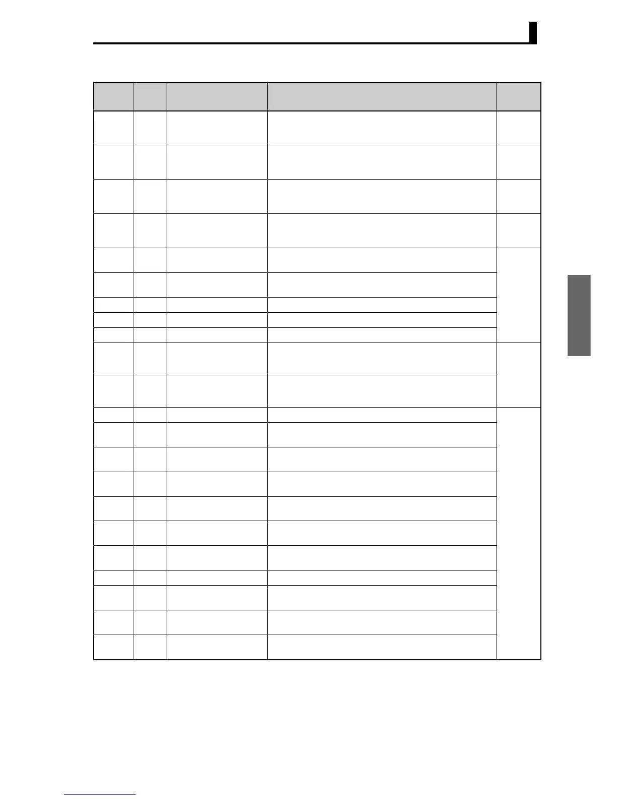
3.1 Variable Area (Setting Range) List
3-9
Note: The alarm function can also be used in Controllers without alarm output terminals. In this case,
confirm alarm occurrences via the status data.
Note 1: Not displayed on the Controller display when Alarm 3 is not assigned to the output.
Note 2: The logic is switched only in the MB command (SYSWAY). The logic of CompoWay/F operation
command code 00 (communications writing) is not affected.
Variable
type
Ad-
dress
Parameter name Setting (monitor) value Level
C3 (83) 0020 Auxiliary Output 2 Open in
Alarm
H'00000000 (0): Close in alarm
H'00000001 (1): Open in alarm
Advanced
function
setting
C3 (83) 0021 Alarm 2 Hysteresis H'00000001 to H'0000270F
(0.1 to 999.9 for TC/Pt universal input models)
(0.01 to 99.99 for Analog input models)
Initial set-
ting
C3 (83) 0022 Auxiliary Output 3 Open in
Alarm (See note 1.)
H'00000000 (0): Close in alarm
H'00000001 (1): Open in alarm
Advanced
function
setting
C3 (83) 0023 Alarm 3 Hysteresis
(See note 1.)
H'00000001 to H'0000270F
(0.1 to 999.9 for TC/Pt universal input models)
(0.01 to 99.99 for Analog input models)
Initial set-
ting
C3 (83) 0024 HB ON/OFF H'00000000 (0): OFF
H'00000001 (1): ON
Advanced
function
setting
C3 (83) 0025 Heater Burnout Latch H'00000000 (0): OFF
H'00000001 (1): ON
C3 (83) 0026 Heater Burnout Hysteresis H'00000001 to H'000001F4 (0.1 to 50.0)
C3 (83) 0027 ST Stable Range H'00000001 to H'0000270F (0.1 to 999.9)
C3 (83) 0028 α H'00000000 to H'00000064 (0.00 to 1.00)
C3 (83) 0029 MV Upper Limit Standard: MV lower limit + 0.1 to H’0000041A (MV lower limit +
0.1 to 105.0)
Heating and cooling: H'00000000 to H'0000041A (0.0 to 105.0)
Adjust-
ment
C3 (83) 002A MV Lower Limit Standard: H’FFFFFFCE to MV upper limit − 0.1 (−5.0 to MV upper
limit − 0.1)
Heating and cooling: H'FFFFFBE6 to H'00000000 (−105.0 to 0.0)
C3 (83) 002B Input Digital Filter H'00000000 to H'0000270F (0.0 to 999.9) Advanced
function
setting
C3 (83) 002C Additional PV Display H'00000000 (0): OFF
H'00000001 (1): ON
C3 (83) 002D MV Display H'00000000 (0): OFF (display of manipulated variable OFF)
H'00000001 (1): ON (display of manipulated variable ON)
C3 (83) 002E Automatic Display Return
Time
H'00000000 (0): OFF
H'00000001 to H'00000063 (1 to 99)
C3 (83) 002F Alarm 1 Latch H'00000000 (0): OFF
H'00000001 (1): ON
C3 (83) 0030 Alarm 2 Latch H'00000000 (0): OFF
H'00000001 (1): ON
C3 (83) 0031 Alarm 3 Latch (See note 1.) H'00000000 (0): OFF
H'00000001 (1): ON
C3 (83) 0032 Move to Protect Level Time H'00000001 to H'0000001E (1 to 30)
C3 (83) 0033 Input Error Output H'00000000 (0): OFF
H'00000001 (1): ON
C3 (83) 0034 Cold Junction Compensa-
tion Method
H'00000000 (0): OFF
H'00000001 (1): ON
C3 (83) 0035 MB Command Logic
Switching (See note 2.)
H'00000000 (0): OFF
H'00000001 (1): ON