9
E5CN-H
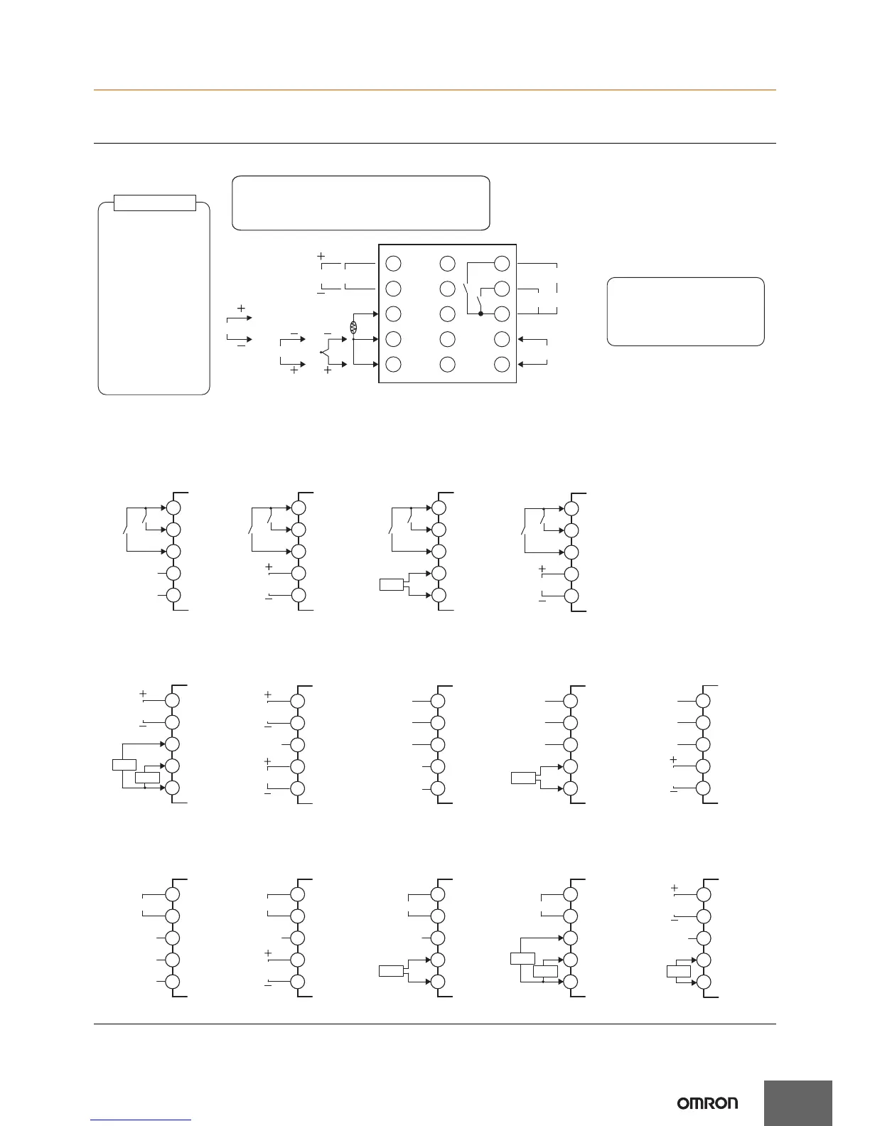
External Connections
• A voltage output (control output, for driving SSR) is not electrically insulated from the internal circuits. When using a grounding thermocouple,
do not connect any of the control output terminals to ground. If the control output terminals are connected to ground, errors will occur in the
measured temperature values as a result of leakage current.
Controllers
Note: Wire all voltage input terminals correctly. The Controller may fail if voltage input terminals are wired incorrectly.
Control output 1
A
B
B
Control output 1
V
DO NOT
USE
DO NOT
USE
DO NOT
USE
mA
Auxiliary outputs
(relay outputs)
?
Input power supply
Auxiliary outputs (relay outputs)
250 VAC, 3 A
(resistive load)
• 100 to 240 VAC
• 24 VAC/VDC (no polarity)
Auxiliary output 2
Auxiliary output 1
6
7
8
9
10
11
12
13
14
15
1
3
2
4
5
Relay output
250 VAC, 3 A
(resistive load)
Voltage output
(for driving SSR)
12 VDC, 21 mA
Linear voltage output
0 to 10 VAC
Load 1 kΩ min.
Current output
0 to 20 mA DC
4 to 20 mA DC
Load 600 Ω max.
A heater burnout alarm, SSR
failure, heater overcurrent alarm,
or input alarm is sent to the
output to which the alarm 1
function is assigned.
RS-232C
CT1
CT1
CT1
11
12
13
14
15
Communications
(RS-232) and CT
11
12
13
14
15
CT2
CT1
Control Output 2
and CT2
11
12
13
14
15
Control Output 2 and
Transfer Output
11
12
13
14
15
EV1
EV2
Event Inputs
E53-CNBN2
E53-CNQHHN2
11
12
13
14
15
CT1
Control Output 2
and CT
E53-CNQHN2 E53-CN03N2 E53-CNQ03N2 E53-CNH03N2 E53-CNHH03N2
E53-CNQFN2 E53-CN01N2 E53-CNH01N2 E53-CNQ01N2
E53-CNQBN2 E53-CNHBN2 E53-CNBFN2
SD
RS-232C
RD
SG
SD
RD
SG
RS-232C
11
12
13
14
15
Communications
(RS-232)
SD
RD
SG
11
12
13
14
15
11
12
13
14
15
RS-485
Communications
(RS-485) and CT
11
12
13
14
15
CT2
CT1
RS-485
Communications
(RS-485) and CT2
Communications (RS-232)
and Control Output 2
11
12
13
14
15
RS-485
Communications (RS-485)
and Control Output 2
11
12
13
14
15
RS-485
Communications
(RS-485)
11
12
13
14
15
EV1
EV2
Event Inputs and
Control Output 2
11
12
13
14
15
EV1
EV2
Event Inputs
and CT
11
12
13
14
15
EV1
EV2
Event Inputs and
Transfer Output
Transfer output
DO NOT
USE
DO NOT
USE
DO NOT
USE
DO NOT
USE
DO NOT
USE
DO NOT
USE
DO NOT
USE
DO NOT
USE
DO NOT
USE
DO NOT
USE
DO NOT
USE
4 to 20 mA DC
(Load 600 Ω
max.)
4 to 20 mA DC
(Load 600 Ω max.)
B (+)
A (−)
B (+)
A (−)
B (+)
A (−)
B (+)
A (−)
Control output 2
12 VDC 21 mA
Control output 2
12 VDC 21 mA
Control output 2
12 VDC 21 mA
Control output 2
12 VDC 21 mA
Transfer output
Control output 2
12 VDC 21 mA
Control output 2
12 VDC 21 mA
The Temperature Controller is set for a K-type
thermocouple (input type = 5) by default. An input error
(s.err) will occur if the input type setting does not agree
with the temperature sensor. Check the input type.
 Loading...