ol-h
100.0
ol-l
0.0
orl
0.0
db
2.0
oc-h
0.8
sqrp
0.0
of-r
50.0
hys
1.0
chys
1.0
mv-r
0.0
mv-e
0.0
Manual Reset Value
Hysteresis (Heating)
Hysteresis (Cooling)
MV at Reset
MV at PV Error
MV Upper Limit
MV Lower Limit
MV Change Rate
Limit
Position Proportional
Dead Band
Open/Close
Hysteresis
Extraction of Square
Root Low-cut Point
plcm
0
M
Communications
Monitor
Work Bit 1 to 8 OFF
Delay
Work Bit 1 to 8 ON
Delay
M
M
M
M
M
M
M
M
M
M
M
M
w1on
0
w1of
0
M
Parameter Mask Enable
Initial Setting/
Communications Protect
Setting Change Protect
Password to Move
to Protect Level
PF Key Protect
pmsk
on
pmov
0
oapt
0
icpt
1
wtpt
off
pfpt
off
prlp
0
Protect Level
Move to Protect Level
Operation/Adjustment
Protect
MM
M
M
M
M
M
s-hc
stnd
cp
20
c-cp
20
orev
or-r
sl-l
-200
t-u
h-m
t-pr
time
pru
m
rtsm
stop
p-on
cont
eset
rst
cntl
pid
pvst
sp
tspu
0
M
in-t
5
in-h
100
in-l
0
dp
0
d-u
c
sl-h
1300
Scaling Upper Limit
Scaling Lower Limit
Decimal Point
Temperature
Unit
SP Upper Limit
SP Lower Limit
Program Time Unit
Step Time/Rate of
Rise Programming
Time Unit of Ramp
Rate
Reset Operation
Startup Operation
Operation End
Operation
PV Start
All PID AT Upper
Limit SP
PID ON/OFF
Standard or
Heating/Cooling
Control Period
(Heating)
Control Period
(Cooling)
Direct/Reverse
Operation
trst
4-20
tr-t
off
tr-h
100.0
tr-l
0.0
ev-1
rr-1
clfl
flot
calb
off
mot
30
vl-c
0
Transfer Output
Signal
Transfer Output
Type
Transfer Output
Upper Limit
Transfer Output
Lower Limit
Event Input
Assignment 1
Close/Floating
Motor Calibration
Travel Time
Valve Completely
Closed Position
vl-o
9999
pms
0
sqr
off
amov
0
Valve Completely
Open Position
Potentiometer
Specification Setting
Extraction of
Square Root
Enable
Moves to Advanced
Function Setting
Level
Input Type
alt1
2
alh1
0.2
M
Alarm 1 to 4
Type
Alarm 1 to 4
Hysteresis
o1st
4-20
Control output
1 to 2 Signal
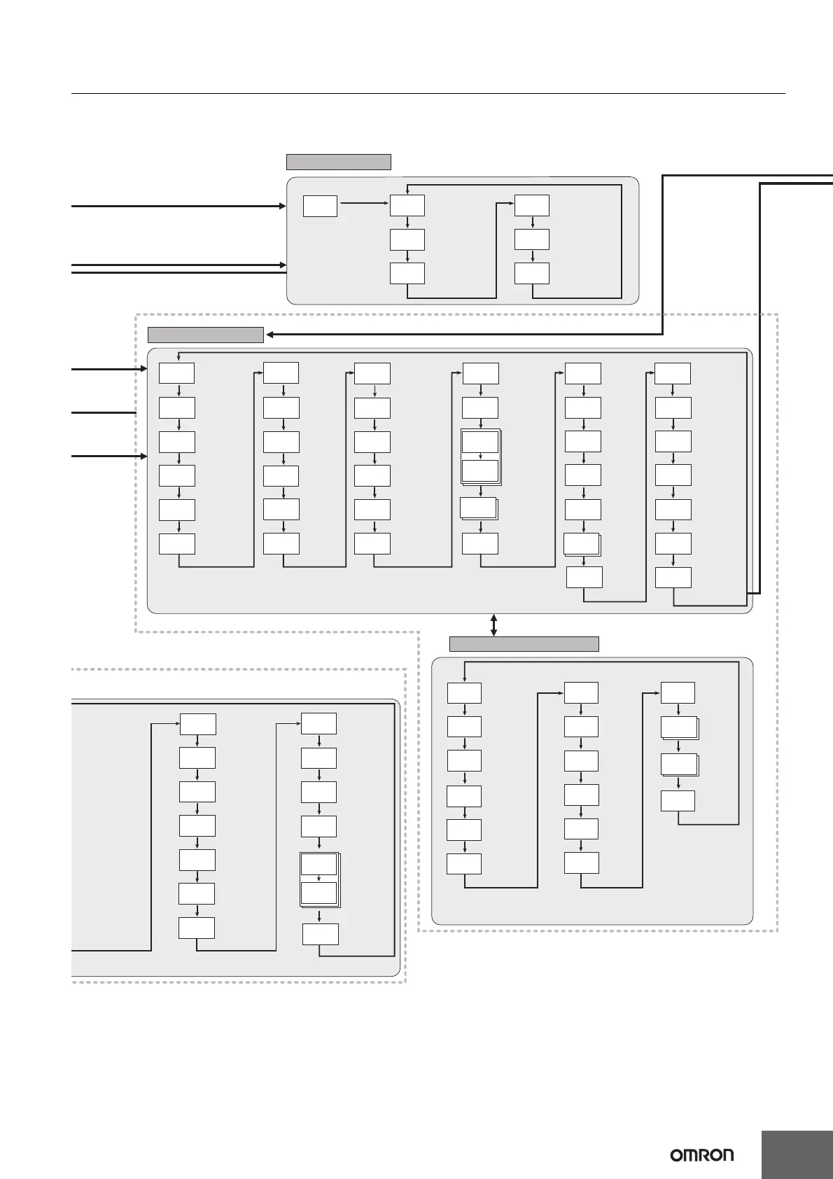
Initial Setting Level
Enter password (−169)
to move.
M
M
M
M
M
M
M
M
M
M
M
M
M
M
M
M
M
ev-2
adv
Event Input
Assignment 2
ev-3
none
Event Input
Assignment 3
to 6
M
M
M
M
M
M
M
M
M
M
M
M
M
M
M
M
M
M
M
*1 When PF Setting = A-M.
*2 When PF Setting = PFDP.
Models with communications only: Changes to settings are applied
when the power is cycled or a software reset is performed.
Protocol Setting
Communications
Unit No.
Communications
Baud Rate
Communications
Data Length
Communications
Stop Bits
Communications
Parity
Send Data
Wait Time
psel
cwf
u-no
1
M
bps
9.6
len
7
sbit
2
sdwt
20
Communications Setting Level
M
M
M
M
M
Highest
Communications
Unit No.
Area
First Address
Upper Word
First Address
Lower Word
Receive Data
Wait Time
Communications
Node Number
Upload
Setting
1 to 23
Download
Setting
1 to 43
Copy
M
maxu
0
area
0
adrh
0
adrl
0
rwat
1000
unit
0
up 1
0
copy
off
M
M
M
M
M
M
M
M
M
M
dn 1
0
prty
even
Press O Key for less than 1 s.
Press O + M Key for at least 1 s.
Press O Key
for at least 1 s.
Press
O
Key
for at least 3 s.
Press
O
Key
for at least 1 s.
Press O Key
for at least 3 s.
Press O + M Key for at least 3 s. (The key pressing
time can be changed in the Move to Protect Level
Time parameter (Advanced Function Setting Level).)
Press O + M Key
for at least 3 s.
 Loading...


