E5DC/E5DC-B
71
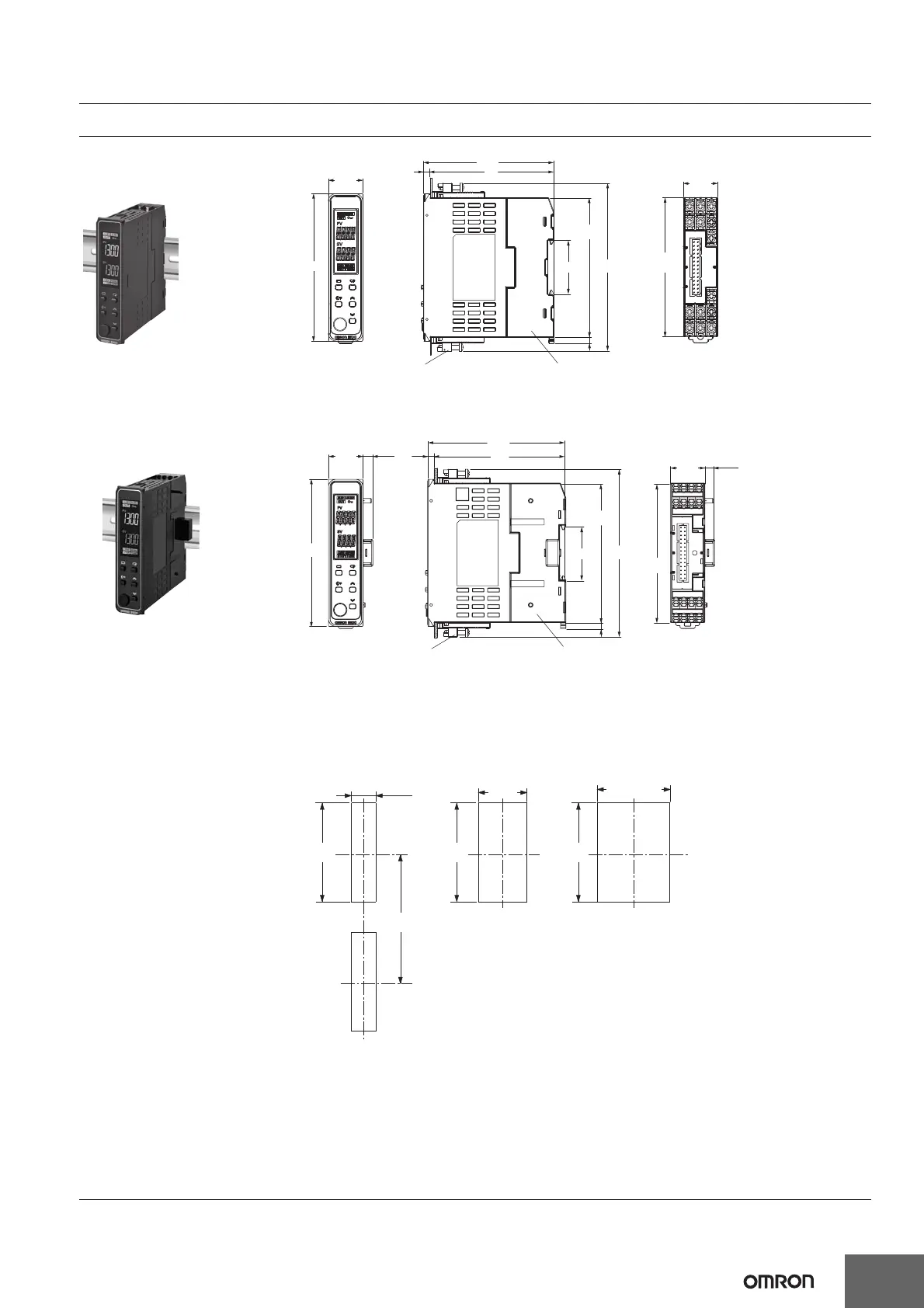
Dimensions (Unit: mm)
Controllers
22.7
+0.3
0
120 min
Mounted Separately Two-Unit Mounting Group Mounted
92
+0.8
0
45
+0.6
0
92
+0.8
0
92
+0.8
0
(22.5 × number of units)
+1.0
0
96
(85)
81
35
22.5
22.5
4
Mounting Adapter
(Y92F-53)(Order separately)
+1.15
-0.2
90
Terminal Unit (E5DC-SCT1S)
110
+1.15
-0.2
4
90
E5DC
• Recommended panel thickness is 1 to 8 mm.
• Group mounting is not possible in the vertical direction. (Maintain the specified mounting space between Controllers.)
• When two or more Digital Temperature Controllers are mounted, make sure that the surrounding temperature does
not exceed the allowable operating temperature specified in the specifications.
The above figure shows the
Terminal Unit attached to
the Main Unit.
4
86
(90)
110
(6.5)
96
22.5
(6.5)
22.5
+1.15
-0.2
90
+1.15
-0.2
4
35
90
Push-In Plus Terminal Unit
(E5DC-SCT1B)
Mounting Adapter
(Y92F-53)(Order separately)
E5DC-B
The above figure shows the
Push-In Plus Terminal Unit
attached to the Main Unit.
• Setup Tool ports are provided as standard feature. Use these ports to connect a computer to the Digital Temperature
Controller. The E58-CIFQ2 USB-Serial Conversion Cable is required to connect to the port on the bottom panel. The
E58-CIFQ2 USB-Serial Conversion Cable and E58-CIFQ2-E Communications Conversion Cable are required to con-
nect to the port on the front panel. (You cannot leave either port connected constantly during operation.)
 Loading...


