M
M
M
M
M
M
M
M
M
M
M
M
M
M
M
M
M
M
M
M
M
M
M
M
M
M
M
M
M
M
M
M
M
M
M
M
M
M
M
M
M
M
M
M
M
M
M
M
M
M
M
M
M
M
M
M
M
M
M
M
M
M
M
M
M
M
M
M
M
M
M
M
M
M
M
M
M
M
M
M
M
M
M
M
M
M
M
M
M
M
M
M
M
M
M
M
M
M
M
SS S S
alt2
2
25
0
init
off
a1lt
off
a2lt
off
rt
off
hsu
on
hsl
off
hsh
0.1
sptr
off
manl
off
pvrp
20
hctm
off
mspu
off
spru
m
rest
a
ret
off
brgt
3
alh2
0.2
alt3
2
alh3
0.2
alt4
2
alh4
0.2
tr-t
off
tr-h
100.0
tr-l
0.0
ev-1
msp0
ev-2
stop
ev-3
none
ev-4
none
ev-5
none
ev-6
none
sqr
off
o1st
4-20
o2st
4-20
trst
4-20
amov
0
sb1n
n-o
sb2n
n-o
sb3n
n-o
sb4n
n-o
hbu
on
hbl
off
hbh
0.1
st-b
15.0
alfa
0.65
tidu
1
at-g
0.8
at-h
0.8
lcma
20.0
inf
0.0
mav
off
o-dp
off
a3lt
off
a4lt
off
prlt
3
a1on
0
a2on
0
a3on
0
a4on
0
a1of
0
a2of
0
a3of
0
a4of
0
mvse
off
amad
off
mant
hold
mani
0.0
cjc
on
lba
0
lbal
8.0
lbab
3.0
out1
o
out2
none
sub1
alm1
sub2
alm2
sub3
alm3
sub4
alm4
alma
49
t-u
m
alsp
sp-m
rs-t
4-20
rspu
off
rsph
1300
rspl
-200
pf
shft
pfd1
1
pfd2
0
pfd3
0
pfd4
0
pfd5
0
spd1
4
spd2
0
odsl
o
pvdp
on
pvst
off
svst
off
d.ref
0.25
cmov
0
ompw
1.0
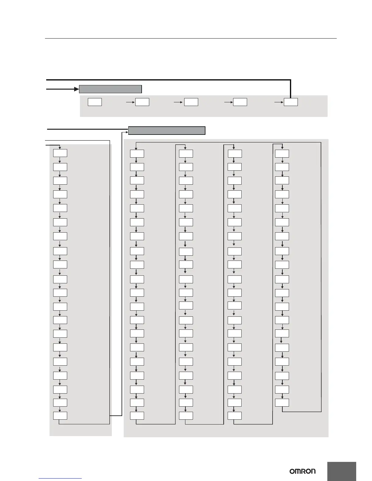
Press the
O
Key for at least 1 s.
Advanced Function Setting Level
Alarm 1 Latch
Alarm 2 Latch
Alarm 3 Latch
Alarm 4 Latch
Move to Protect Level
Time
HS Alarm Latch
HS Alarm Hysteresis
LBA Detection Time
LBA Level
LBA Band
Control Output 1
Assignment
Control Output 2
Assignment
HS Alarm Use
RT
Parameter Initialization
Heater Burnout Latch
Number of Multi-SP
Points
SP Ramp Time Unit
Standby Sequence
Reset
Auxiliary Output 1
Open in Alarm
Auxiliary Output 2
Open in Alarm
Auxiliary Output 3
Open in Alarm
Auxiliary Output 4
Open in Alarm
Heater Burnout
Hysteresis
HB ON/OFF
PF Setting
Monitor/Setting Item 1
Monitor/Setting Item 2
Monitor/Setting Item 3
"PV/SP (1)" Display
Screen Selection
MV Display Selection
PV Decimal Point
Display
PV Status Display
Function
SV Status Display
Function
Monitor/Setting Item 4
Monitor/Setting Item 5
"PV/SP (2)" Display
Screen Selection
Move to Calibration
Level
Input Digital Filter
ST Stable Range
α
Integral/Derivative
Time Unit
AT Calculated Gain
AT Hysteresis
Limit Cycle MV
Amplitude
Alarm 1 ON Delay
Alarm 2 ON Delay
Alarm 3 ON Delay
Alarm 4 ON Delay
Alarm 1 OFF Delay
Alarm 2 OFF Delay
Alarm 3 OFF Delay
Auxiliary Output 1
Assignment
Auxiliary Output 2
Assignment
Soak Time Unit
Alarm SP Selection
Auxiliary Output 2
Assignment
Auxiliary Output 4
Assignment
(E5EC only)
Integrated Alarm
Assignment
Remote SP Input Type
Remote SP Enable
Remote SP Upper limit
Remote SP Lower limit
Moving Average Count
MV at Stop and Error
Addition
Auto/Manual Select
Addition
Manual Output Method
Manual MV Initial Value
Alarm 4 OFF Delay
Monitor/Setting
Item Display 1
Note: The monitor/setting items to be displayed is set in the Monitor/Setting Item 1 to 5 parameters (advanced function setting level).
Monitor/Setting
Item Display 2
Monitor/Setting
Item Display 3
Monitor/Setting
Item Display 4
Monitor/Setting
Item Display 5
Monitor/Setting Item Level
Alarm 2 Type
Alarm 4 Type
Transfer Output Type
Transfer Output
Upper Limit
Transfer Output
Lower Limit
Move to Advanced
Function Setting Level:
Linear output
Displayed when initial setting/
communications protect is set to 0.
Extraction of Square
Root Enable
Move by setting password (−169).
Event Input
Assignment 1
Event Input
Assignment 2
Alarm 4 Hysteresis
Alarm 2 Hysteresis
Event Input
Assignment 3
Event Input
Assignment 4
Display Refresh Period
Manual MV Limit
Enable
PV Rate of Change
Calculation Period
Heating/Cooling
Tuning Method
Minimum Output
ON/OFF Band
SP Tracking
Automatic Display
Return Time
Display Brightness
MV Display
Alarm 3 Type
Alarm 3 Hysteresis
Event Input
Assignment 5
Event Input
Assignment 6
Control Output 1
Signal Type
Control Output 2
Signal Type
Transfer Output
Signal Type
(E5EC only)
(E5EC only)
Cold Junction
Compensation Method