M
M
M
M
M
M
M
M
M
M
M
M
M
M
M
M
M
M
M
M
M
M
M
M
M
M
M
M
M
M
M
M
M
M
M
M
M
M
M
M
M
M
M
M
M
M
M
M
M
M
M
M
M
M
M
M
M
M
M
M
M
M
M
M
M
M
M
M
M
M
M
M
M
M
M
M
M
M
M
M
M
M
M
M
M
M
M
M
M
M
M
M
M
M
M
M
M
M
pmsk
on
25
0
C
25
0
l.adj
ins
0.0
rss
0.0
inrt
1.000
rsrt
1.000
c-p
8.0
c-i
233
c-d
40
M
M
M
p
8.0
i
233
d
40
c-db
0.0
of-r
50.0
hys
1.0
chys
1.0
soak
1
wt-b
off
mv-s
0.0
pmov
0
oapt
0
icpt
1
wtpt
off
pfpt
off
M
M
chgp
off
M
prlp
0
mv-e
0.0
sprl
same
M
sprt
off
w1on
w2on
w3on
w4of
w5on
w6on
w7on
w8on
w1of
w2of
w3of
w4on
w5of
w6of
w7of
w8of
ol-h
100.0
ol-l
0.0
M
M
orl
0
sqrp
0
at
off
cmwt
off
ct1
0.0
M
spmd
lsp
hb1
0.0
ct2
0.0
hb2
0.0
lcr1
0
hs1
50.0
lcr2
0
hs2
50.0
sp-0
0
sp-1
0
sp-2
0
sp-3
0
sp-4
0
sp-5
0
sp-6
0
sp-7
0
M
sp-3
0
r-s
run
in-t
5
in-h
100
in-l
0
dp
0
d-u
c
sl-h
1300
sl-l
-200
cntl
onof
s-hc
stnd
st
on
ptrn
off
cp
20
c-cp
20
orev
or-r
alt1
2
alh1
0.2
al-1
0
al1h
0
al1l
0
al-2
0
al2h
0
al2l
0
al-4
0
al4h
0
al4l
0
M
M
M
al-3
0
al3h
0
al3l
0
o
0.0
c-o
0.0
25
0
a-m
m-sp
0
sp-m
0
rsp
0.0
ct-1
0.0
ct-2
0.0
lcr1
0.0
lcr2
0.0
prst
rset
M
sktr
0
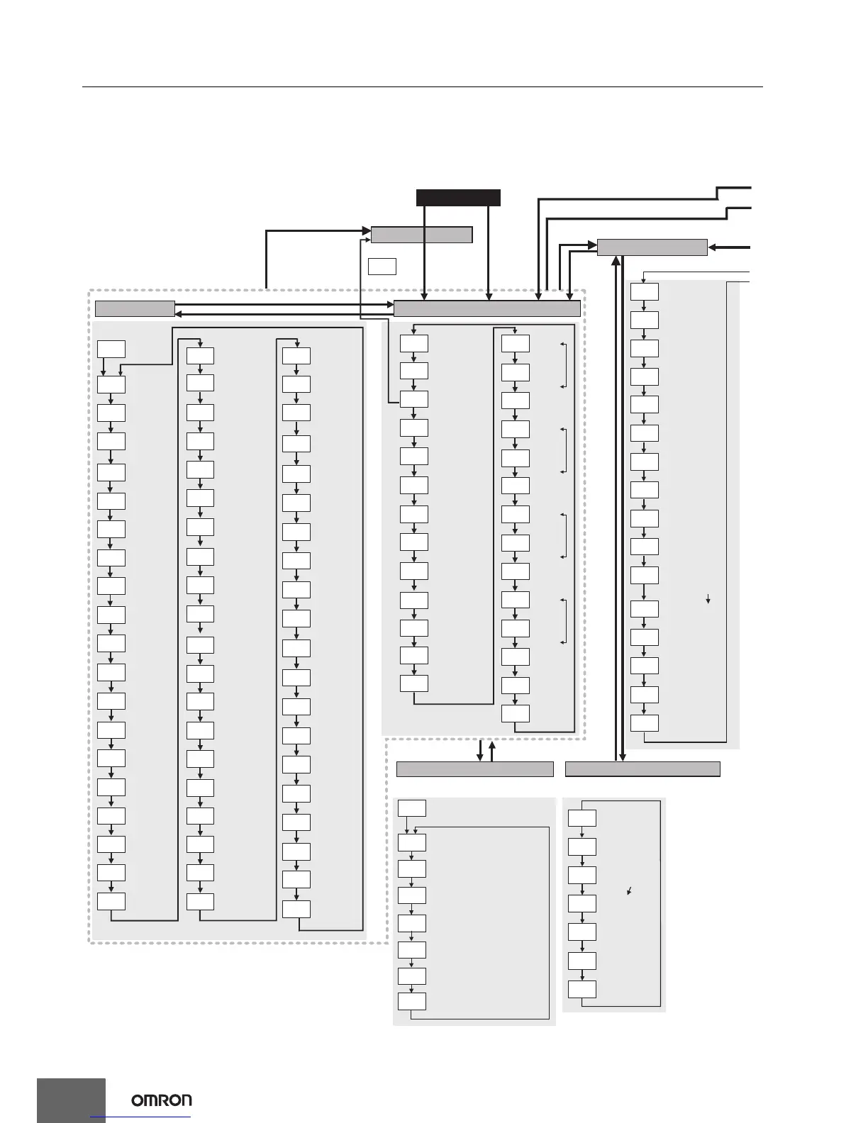
PID
Control
only
Press the
O
Key for at least 3 s.
Press the
O
Key
for at least
1 s.
Press the
S
Key
for at least 1 s. *1
Press the
O
Key or the
S
Key for at least
1 s. *1
Initial Setting Level
Operation Level
Power ON
Starting in manual mode.
Adjustment Level
Press the
O
Key less than 1 s.
Press the
O
Key less than 1 s.
Other than the Auto/Manual Switch display
PV/MV
Starting in
automatic
mode.
Adjustment Level Display
Displayed only once when
entering adjustment level.
Manual Control Level
Press the
O
Key less than 1 s.
Press the
S
Key *2
Press the
S
Key *2
Press the
O Key
for at
least 3 s.
Parameter Mask Enable:
Press the
O Key
less than
1 s.
Press the O and M Keys
for at least 3 s.
Proportional Band
(Cooling)
ST
Communications Setting Level
Note: Displayed only for models with communications. Changes
are effective after cycling power or after a software reset.
Protect Level
Note: The time ta ken to move to the protect level can be
adjusted by changing the "Move to protect level time" setting.
Move to Protect Level:
Operation/Adjustment Protect:
Initial Setting/Communications Protect:
Setting Change Protect:
Password to Move to Protect Level:
Password
Password setting
Displayed only when a password is set.
Restricts moving to protect level.
Restricts displaying and modifying menus in
operation, adjustment, and manual control levels.
This protect level restricts movement to the initial
setting, communicationssetting, and advanced
function setting levels.
Protects changes to setups by
operating the front panel keys.
Displayed only when a
parameter mask is set.
PF Key Protect
Input Type
Control Period (Heating)
Scaling Upper Limit
Scaling Lower Limit
Decimal Point
Temperature Unit
SP Upper Limit
SP Lower Limit
PID ON/OFF
Standard or
Heating/Cooling
Program Pattern
Control Period (Cooling)
Direct/Reverse Operation
For input type of analog
Limit the set point
For input type of
temperature, standard
control, or PID
Set the ON/OFF
output cycle.
Temperature for
°C or °F input type.
When assigning PID
or control output to
ON/OFF output
AT Execute/Cancel
Communications
Writing
Heater Current 1
Value Monitor
Heater Current 2
Value Monitor
Leakage Current
1 Monitor
Leakage Current
2 Monitor
Heater Burnout
Detection 1
Heater Burnout
Detection 2
HS Alarm 1
HS Alarm 2
SP 0
SP 1
SP 2
SP 3
SP 4
SP 5
SP 6
SP 7
Integral Time
(Cooling)
Derivative Time
(Cooling)
Dead Band
Manual Reset Value
Clear the offset during
stabilization of P or PD
control.
Hysteresis (Heating)
Hysteresis (Cooling)
Soak Time
Wait Band
MV at Stop
MV at PV Error
Work Bit 1 ON
Delay
Work Bit 2 ON
Delay
Work Bit 3 ON
Delay
Work Bit 4 OFF
Delay
Work Bit 5 ON
Delay
Work Bit 6 ON
Delay
Work Bit 7 ON
Delay
Work Bit 8 ON
Delay
Work Bit 1 OFF
Delay
Work Bit 2 OFF
Delay
Work Bit 3 OFF
Delay
Work Bit 4 ON
Delay
Work Bit 5 OFF
Delay
Work Bit 6 OFF
Delay
Work Bit 7 OFF
Delay
Work Bit 8 OFF
Delay
MV Upper Limit
MV Lower Limit
Hysteresis settings
Process Value
Input Shift
Remote SP Input Shift
PV Input Slope
Coefficient
Remote SP input Slope
Coefficient
SP Ramp Fall Value
Process Value/Set
Point (1)
Process Value/Set
Point (2)
Auto/Manual Switch
PID 1 control only.
Added for Auto/Manual
Switch Display Addition.
Set Point During SP
Ramp
Heater Current 1 Value
Monitor
Heater Current 2 Value
Monitor
Leakage Current 1
Monitor
Leakage Current 2
Monitor
Program Start
Multi-SP Set Point
Setting
Alarm
Value 1
Alarm Value
Upper Limit 1
Alarm Value
Lower Limit 1
Alarm
Value 2
Alarm Value
Upper Limit 2
Alarm Value
Lower Limit 2
MV Monitor
(Heating)
MV Monitor
(Cooling)
Press the O and M Keys
for at least 1 s.
Alarm 1
Hysteresis
Alarm 1 Type
*1. When the PF
Setting parameter
is set to A-M.
*2. When the PF
Setting parameter
is set to PFDP.
M
M
M
M
M
M
M
psel
cwf
u-no
1
bps
9.6
len
7
sbit
2
prty
even
sdwt
20
Protocol Setting:
Communications
Unit No.
Communications
Baud Rate
Communications
Data Length
Communications
Stop Bits
Communications Parity
Send Data Wait Time
CompoWay/F only
Switches between
CompoWay/F and
Modbus.
Proportional Band
Integral Time
Derivative Time
PID settings
SP Ramp Set Value
Extraction of Square
Root Low-cut Point
MV Change
Rate Limit
SP Mode
RUN/STOP
Remote SP Monitor
Soak Time Remain
Display Changed Parameters
Set either of these parameters. Set either of these parameters.
Alarm
Value 3
Alarm Value
Upper Limit 3
Alarm Value
Lower Limit 3
Set either of these parameters.
Alarm
Value 4
Alarm Value
Upper Limit 4
Alarm Value
Lower Limit 4
Set either of these parameters.
 Loading...


