E5EC
9
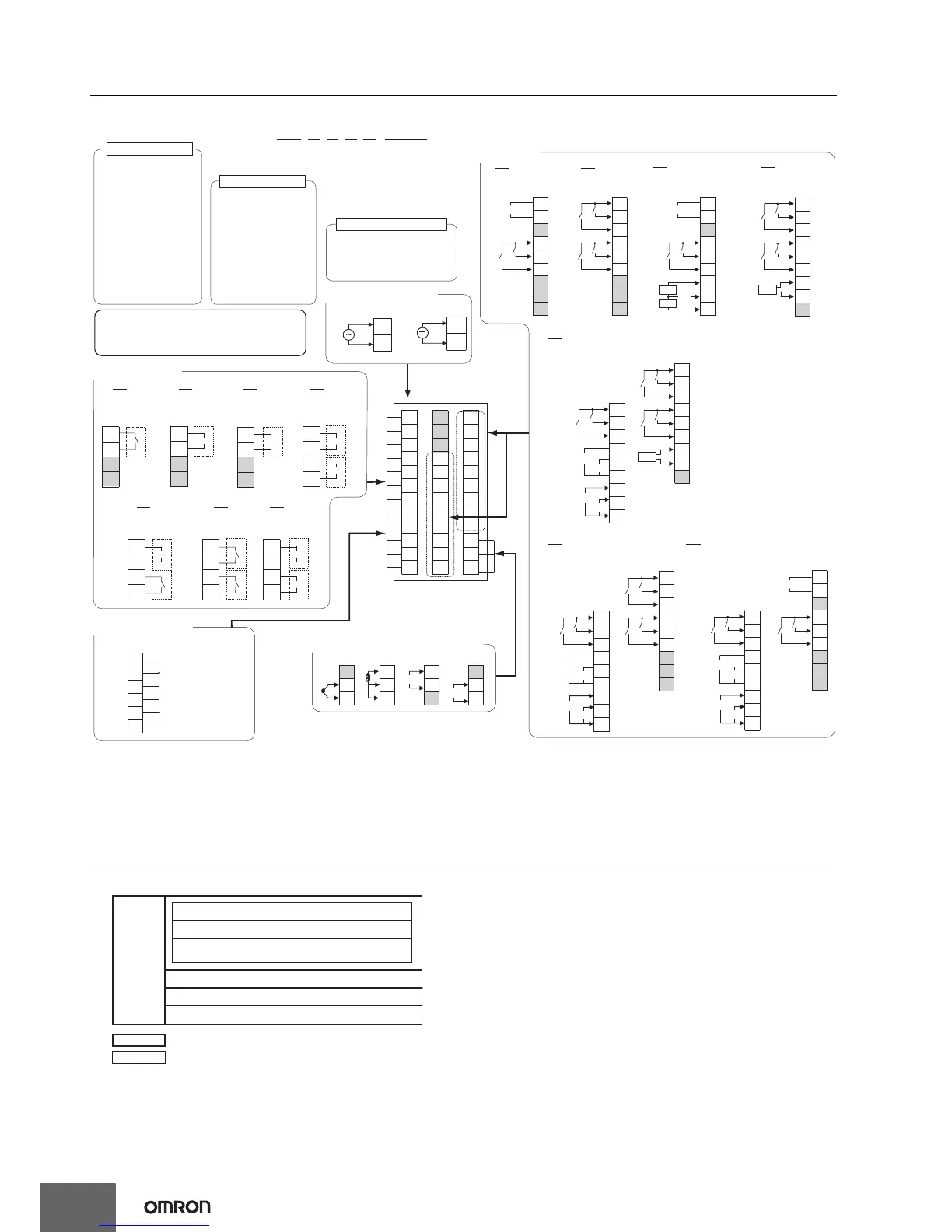
External Connections
E5EC
Note: 1. The application of the terminals depends on the model.
2. Do not wire the terminals that are shown with a gray background.
3. When complying with EMC standards, the cable that connects the sensor must be 30 m or less. If the cable length exceeds 30 m,
compliance with EMC standards will not be possible.
4. Connect M3 crimped terminals.
Isolation/Insulation Block Diagrams
Models with 4 Auxiliary Outputs
The E5EC is set for a K-type thermocouple (input
type = 5) by default. An input error (s.err) will occur
if the input type setting does not agree with the
temperature sensor. Check the input type.
Relay output
250 VAC, 5 A
(resistive load)
Voltage output
(for driving SSR)
12 VDC, 40 mA
When There Is a
Control Output 2:
21 mA
Current output
0 to 20 mA DC
4 to 20 mA DC
Load: 500 Ω max.
23
24
11
12
35
36
19
20
21
22
9
10
31
32
33
34
2
25
7
8
175
6
29
30
3
4
26
27
28
113
14
15
16
18
2
1
2
100 to 240 VAC
1
24 VAC/VDC
V
-
23
V
24
+
22
TC
22
+
-
m
-
+
23
22
23
24
Pt I
24
22
23
24
A
B
B
7
8
11
12
Auxiliary outputs 1, 2, 3, 4
9
10
Auxiliary output 2
Auxiliary output 1
Auxiliary output 4
Auxiliary output 3
-
+
21
+
+
+
-
19
20
16
17
18
011
6 event Inputs, 1 CT input,
transfer output, and remote SP input
13
14
15
29
30
31
32
35
36
33
34
28
V
mA
V
I
35
-
34
33
32
31
30
29
28
+
+
+
+
013
6 event Inputs, transfer
output, and remote SP input
13
14
15
16
17
18
19
20
21
36-
V
mA
V
I
014
Communications, 4 event Inputs,
transfer output, and remote SP input
28
29
30
32
31
33
13
14
15
16
17
18
19
20
21
+
-
+
34+
+
35
36-
V
mA
V
I
EV1
EV2
EV1
EV2
EV1
EV2
EV3
EV4
EV3
EV4
EV5
EV6
EV5
EV6
EV5
EV6
B(+)
A(-)
RS-485
CT1
21
19
19
20
20
21
17
19
20
21
16
17
18
13
13
14
14
15
15
16
17
18
15
16
010
4 event inputs
and 1 CT input
009
Communications, 2 event
inputs, and 2 CT inputs
13
14
004
Communications
and 2 event inputs
18
005
4 event inputs
19
20
21
13
14
15
17
18
16
EV1
EV2
EV1
EV2
EV1
EV2
EV1
EV2
EV3
EV4
EV3
EV4
B(+)
A(-)
RS-485
B(+)
A(-)
RS-485
CT1
CT2
COM
CT1
Transfer
output
Remote
SP
Transfer
output
Transfer
output
Remote
SP
Remote
SP
↑
Terminal type
Auxiliary outputs 1 to 4
Control output 2
Control output 1
Relay output
Models with 4 auxiliary
outputs: 250 VAC, 2 A
(resistive load)
Relay output
250 VAC, 5 A
(resistive load)
Voltage output
(for driving SSR)
12 VDC, 21 mA
Current output
0 to 20 mA DC
4 to 20 mA DC
Load: 500 Ω max.
-
+
+
+
+
++
-
-
+
-
-
-
-
(1) Control output
Models with
1 Relay
Output
Models with 1
Voltage Output
(for Driving SSR)
Models with 2
Voltage Outputs
(for Driving SSR)
Models with Voltage
Output (for Driving SSR)
and Relay Output
Models with 2
Relay Outputs
Models with 2
Current Outputs
Models with 1
Current Output
3
4
5
6
3
4
5
6
3
4
5
6
3
4
5
6
3
4
5
6
3
4
5
6
3
4
5
6
RX
R
R
R
R
Q
Q
Q
Q
OUT1
OUT1
OUT1
OUT1
OUT2
C
C
C
QR
RR CC
QX CX
QQ
(2) Auxiliary Outputs
(3) Input Power Supply
(6) Options
(5) Sensor (Temperature/Analog) Input
(no polarity)
E5EC-@@ 4 @ 5 M - @@@
(1) (2) (3) (4) (5) (6)
Sensor input, CT inputs, and remote SP input
Communications and event inputs
Voltage output (for driving SSR),
current output, and transfer output
Relay output
Auxiliary outputs 1, 2
Auxiliary outputs 3, 4
: Reinforced insulation
: Functional isolation
Power
Supply