EJ1
15
Nomenclature and Specification Settings
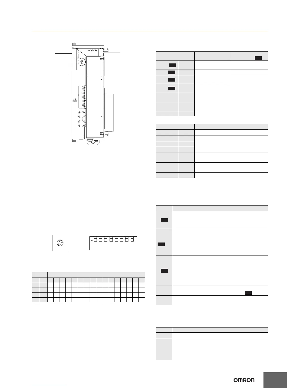
Part Names
Operation Indicators
EJ1N-TC2/TC4
EJ1N-HFU@-NFL@
* Some time is required for the indicators to light after the power is
turned ON.
Specification Settings
Switch Operation
• Check that the EJ1 is turned OFF before operating any switch
other than pin 6 of SW2. Settings are read only when power is
turned ON.
• Set the switches with a small flat-blade screwdriver. Do not set the
switches midway between settings.
• SW1 is set to 1 and SW2 pins are all set to OFF in the default
settings.
Setting the Unit Number
SW1 and SW2 are used together to set the unit number to between
00 and 63. The factory setting is unit number 01.
SW2 Settings
EJ1N-TC2/TC4
Note: Make sure power to the Unit is turned OFF before making
settings for any pin other than pin 6.
Pin 6 can be turned ON or OFF while the power is ON.
EJ1N-HFU@-NFL@
COM1
COM2
COM3
PWR
RUN
ERR
ALM
1
2
3
4 OUT
SW2
6
OUT
OPN
21345678
EJ1N-TC
SW1
ON
OPN
0
1
2
3
4
5
6
7
8
9
A
B
C
D
E
F
SW1
SW2
Operation
Indicators
COM1
COM2
COM3
Operation
Indicators
PWR 1
RUN 2
ERR 3
ALM 4
Operation Indicators
Meaning: When SW2
No. 6 is OFF
Meaning: When SW2
No. 6 is ON
PWR/1 green
Lights when the power
is ON.
Lit when output 1 is ON.
RUN/2 green Lights during operation. Lit when output 2 is ON.
ERR/3 red
Flashes or lights when
an error occurs.
Lit when output 3 is ON.
ALM/4 red
Lights when an alarm is
activated.
Lit when output 4 is ON.
COM 1 orange
Flashes during communications via port A on the
End Unit.
COM 2 orange
Flashes during communications via port B on the
End Unit.
COM 3 orange Flashes during communications with the G3ZA.
Operation Indicators
Meaning
PWR
green
Lit while the power is ON. *
RUN
green
---
ERR
red
Flashes or lights when an error occurs.
ALM
red
Lights when an alarm is activated.
COM 1
orange
Flashes during communications via port A
on the End Unit.
COM 2
orange
Flashes when the EJ1 system is in
operation.
COM 3
orange
Flashes during communications via port C.
V1.2
V1.2
V1.2
V1.2
V1.2
SW2 SW1
1 2 0 1 2 3 4 5 6 7 8 9 A B C D E F
OFF OFF
00 01 02 03 04 05 06 07 08 09 10 11 12 13 14 15
ON
OFF
16 17 18 19 20 21 22 23 24 25 26 27 28 29 30 31
OFF
ON 32 33 34 35 36 37 38 39 40 41 42 43 44 45 46 47
ON ON 48 49 50 51 52 53 54 55 56 57 58 59 60 61 62 63
0
1
2
3
4
5
6
7
8
9
A
B
C
D
E
F
ON
21345678
SW1SW2
SW2 Meaning
3
Set to ON when using the Modbus communications
protocol for port B.
OFF:
The setting for port B communications protocol is used.
ON: Modbus is used.
4 to 5
Set the baud rate of port B.
4 = OFF, 5 = OFF:Use the baud rate parameter setting
for port B (default: 9.6 kbps).
4 = ON, 5 = OFF: 19.2 kbps
4 = OFF, 5 = ON: 38.4 kbps
4 = ON, 5 = ON: 115.2 kbps
6
Set to ON to display the output status on the operation
indicators.
OFF: The operation status is displayed (PWR, RUN,
ERR, and ALM).
ON:
The output status is displayed (outputs 1, 2, 3, and 4).
Note: Normally keep this pin set to OFF so that the
operation status can be checked.
7
ON: G3ZA Multi-channel Power Controller in operation
ON when using a G3PW Power Controller.
8
Use when an HFU is used and Units are distributed.
(Refer to the User's Manual for details.)
SW2 Meaning
3 to 7 Not used (OFF)
8
• EJ1N-HFU@-NFLK
OFF: RS-485 is selected.
ON: RS-232C is selected.
• EJ1N-HFU@-NFL2
OFF (Not used.)
V1.2
V1.2
V1.2
V1.1

 Loading...


