EJ1
21
Precautions for Correct Use
Installation
1. Do not connect the End Unit directly to an HFU.
2. Connect the End Unit to the right side of a Basic Unit.
3. Connect the HFU to the left side of the Basic Units.
4. Connection is not possible to CJ1-series PLCs.
5. Use the EJ1G-@@ for gradient temperature control. When not
using gradient temperature control, use the EJ1N-@@.
6. When removing the terminal block to replace a Unit, be sure that
the new Unit is the same as the Unit that is being replaced.
Service Life
1. Use the product within the following temperature and humidity
ranges:
Temperature: −10°C to 55°C (with no condensation or icing)
Humidity: 25% to 85%
When the Temperature Controller is incorporated in a control
panel, make sure that the controller's ambient temperature and not
the panel's ambient temperature does not exceed 55°C.
2. The service life of electronic devices like Temperature Controllers
is determined not only by the number of times the relay is switched
but also by the service life of internal electronic components.
Component service life is affected by the ambient temperature: the
higher the temperature, the shorter the service life and the lower
the temperature, the longer the service life. Therefore, the service
life can be extended by lowering the temperature of the
Temperature Controller.
3. Mounting two or more Temperature Controllers side by side, or
mounting Temperature Controllers above each other may cause
heat to build up inside the Temperature Controllers, which will
shorten their service life. If the Temperature Controllers are
mounted above each other or side by side, use forced cooling by
fans or other means of air ventilation to cool down the
Temperature Controllers.
However, be sure not to cool only the terminals. Doing so will
result in measurement errors.
Ensuring Measurement Accuracy
1.
When extending or connecting the thermocouple lead wire, be sure to
use compensating wires that match the thermocouple types.
2.
When extending or connecting the lead wire of the platinum resistance
thermometer, be sure to use wires that have low resistance and keep
the resistance of the three lead wires the same.
3. Mount the Temperature Controller so that it is horizontally level.
4. If the measurement accuracy is low, check to see if input shift has
been set correctly.
Precautions for Operation
1. A certain amount of time is required for the outputs to turn ON from
the time the power supply is turned ON. Due consideration must
be given to this time when incorporating Temperature Controllers
in a sequence circuit.
2.
It takes 30 minutes from the time the Temperature Controller is turned
ON until the current temperature is displayed. Always turns ON the
power supply at least 30 minutes before starting temperature control.
3.
Avoid using the Temperature Controller near a radio, television set, or
other wireless device. Its use would result in reception disturbance.
Wiring Screw-Less Clamp Terminals
There are two holes for each terminal. The
hole on the right is the operation hole and the
hole on the left is the wire hole.
Insert a flat-blade screwdriver with a width of
2.5 mm into the operation hole, insert the wire
into the wire hole, and then remove the
screwdriver. The wire will be clamped.
Use pin terminals that are suitable for the
cross-sectional area of the wire.
Recommended pin terminals:
Weidmuller H-sleeve series
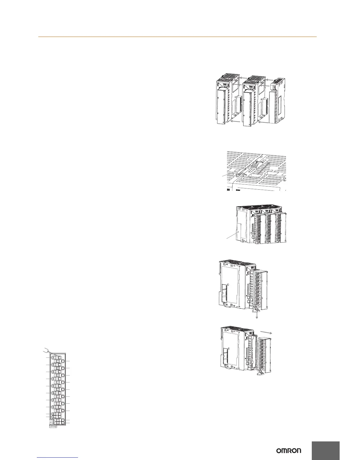
Installation
Connecting Units
1. Align the connectors and connect the Units to each other. Connect
an End Unit to the Unit on the right end.
Note: 1. Do not connect the End Unit directly to an HFU.
2. Connect the End Unit to the right side of a Basic Unit.
2. Slide the yellow sliders on the top and bottom of the Units until they
click into place.
3. Attach the cover seal to the connector opening on the Unit on the
left end of the EJ1.
Removing the Terminal Block
1. Press down the terminal block lever.
2. Pull out the terminal block.
B2
B3
B4
B5
B6
B7
B8
B1
A1
A2
A3
A4
A5
A6
A7
A8
B9
B10
A9
A10
Slider
Lock
Cover Seal
Lower the lever.
Pull out.

 Loading...


