22
EJ1
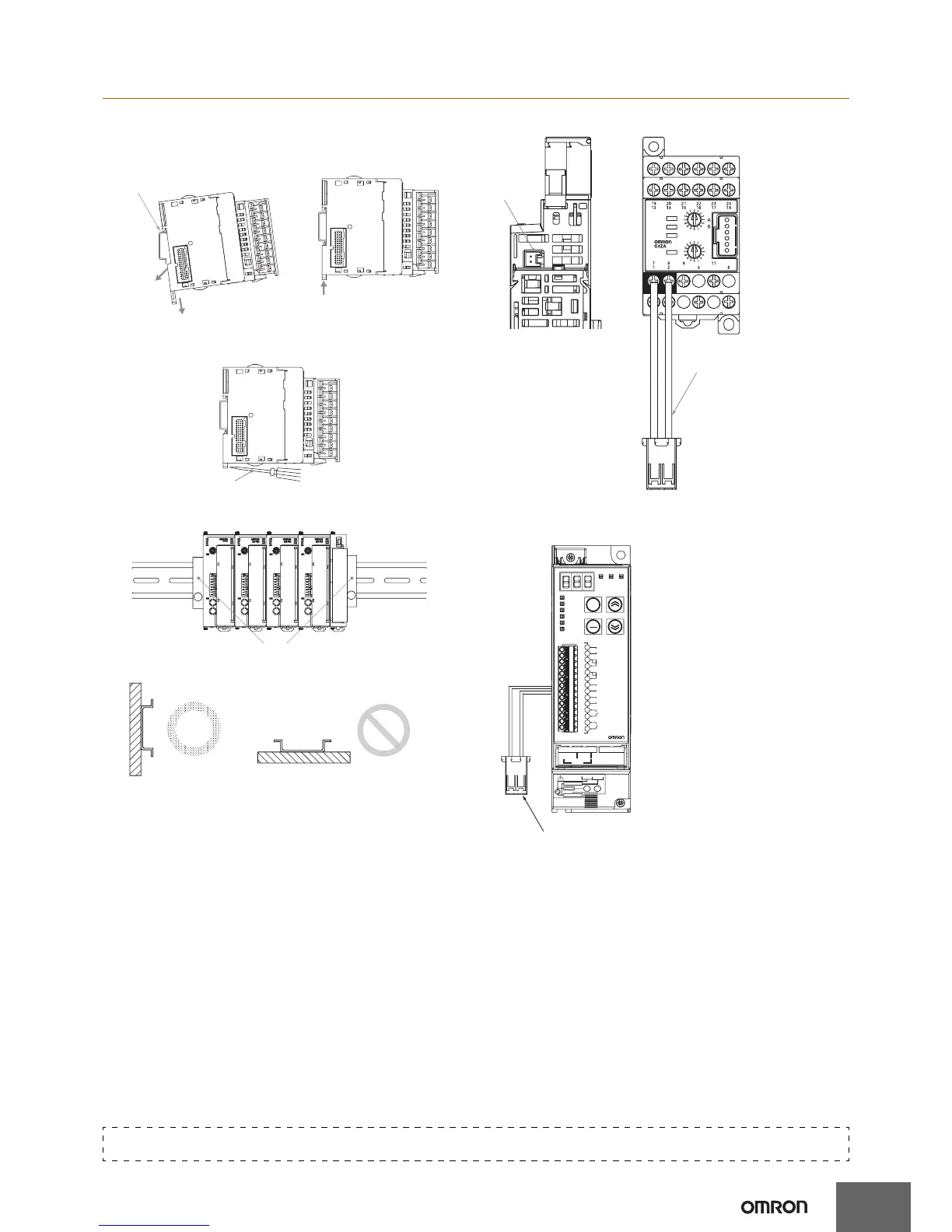
Mounting to the DIN Rail
Mounting
Catch the hook located on the top of the Unit onto the DIN Rail and
press the Unit until the Unit locks into place.
Dismounting
Pull down on the hook with a flat-blade screwdriver and lift up on the
Unit.
Mount one End Plate to each side of the EJ1C-EDU (PFP-M End
Plates are included with the End Unit).
Install the DIN Rail vertically to the ground.
Applicable DIN Rail (sold separately): PFP-100N (100 cm),
PFP-50N (50 cm)
Connecting to the G3ZA (EJ1N-TC)
Refer to the “G3ZA Instruction Manual” for wiring methods.
Connecting to the G3PW (EJ1N-TC)
Refer to the G3PW Instruction Manual for wiring methods.
(1) Lower the hooks.
(3) Press in
on the
Unit.
(2) Catch the upper hook
onto the DIN Rail.
(4) Make s
ure the Unit
is locked into place.
Flat-
blade Screwdriver
PFP-M
Correct
Incorrect
Vertically Horizontally
SW2
SW1
ERROR
OCC
SD/RD
READY
CN1
Connect the G3ZA
Connecting Cable to the
CN1 connector on the
bottom of the TC Unit.
G3ZA
CN1
EJ1C-CBLA050 (Sold Separately)
(cable length: 5 m)
Connect the black line with a
white stripe to terminal 7 on the
G3ZA and the black line with no
stripe to terminal 8.
G3PW
%(IN)
%(DUTY)
%(OUT)
%(PHASE)
A
COMM
ADJ SET
EV
RST
ENT
LVL
100-240VAC
4-20mA
See
Manual
Time-lag fuse
Load
Fast-acting fuse
1-5V
+-
+
-
LN
T1
N L
L1
43215
G3PW
RS-485
B(+)
A(-)
DUTY SET
REMOTE SET
EVENT
RESET
ALARM1(NPN)
ALARM2(NPN)
+
-
+
-
14
13
12
11
10
9
8
7
6
5
4
3
2
1
Connect the black line with a white stripe to terminal 1 on
the G3PW and the black line with no stripe to terminal 2.
Set the baud rate to 57.6 kbps
(default value) using key
operations. For details, refer to
the G3PW Operation Manual.
EJ1-CBLA050 (order separately) (cable length: 5 m)
Refer to the following manual for precautionary information and other information necessary to use the EJ1:
EJ1 Modular Temperature Controller User’s Manual (Cat. No. H142)

 Loading...


