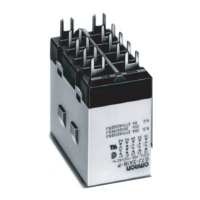
Power Relay G7J A-59
Electromechanical
Relays
Specifications
■ Coil Ratings
Note: 1. The rated current and coil resistance are measured at a coil temperature of 23°C with tolerances of +15%/–20% for AC rated current and
±15% for DC coil resistance. (The values given for AC rated current apply at 50 Hz or 60 Hz.)
2. Performance characteristic data are measured at a coil temperature of 23°C.
3. The maximum voltage is one that is applicable to the Relay coil at 23°C.
■ Contact Ratings
Note: The values in parentheses indicate values for a bifurcated contact.
■ Characteristics
Rated voltage Rated current Coil resistance Must-operate
voltage
Must-release
voltage
Max. voltage Power
consumption
AC 24 VAC 75 mA --- 75% max. of rated
voltage
15% min. of rated
voltage
110% of rated
voltage
Approx. 1.8 to
2.6 VA
50 VAC 36 mA ---
100 to 120 VAC 18 to 21.6 mA ---
200 to 240 VAC 9 to 10.8 mA ---
DC 6 VDC 333 mA 18 Ω 10% min. of rated
voltage
Approx. 2.0 W
12 VDC 167 mA 72 Ω
24 VDC 83 mA 288 Ω
48 VDC 42 mA 1,150 Ω
100 VDC 20 mA 5,000 Ω
Item Resistive load (cos φ = 1) Inductive load (cosφ = 0.4) Resistive load
Contact mechanism Double break
Contact material Ag alloy
Rated load NO: 25 A at 220 VAC (24 A at 230 VAC)
NC: 8 A at 220 VAC (7.5 A at 230 VAC)
NO: 25 A at 30 VDC
NC: 8 A at 30 VDC
Rated carry current NO: 25 A (1 A)
NC: 8 A (1 A)
Max. switching voltage 250 VAC 125 VDC
Max. switching current NO: 25 A (1 A)
NC: 8 A (1 A)
Contact resistance (see note 2) 50 mΩ max.
Operate time (see note 3) 50 ms max.
Release time (see note 3) 50 ms max.
Max. operating frequency Mechanical: 1,800 operations/hr
Electrical: 1,800 operations/hr
Insulation resistance (see note 4) 1,000 MΩ min. (at 500 VDC)
Dielectric strength 4,000 VAC, 50/60 Hz for 1 min between coil and contacts
4,000 VAC, 50/60 Hz for 1 min between contacts of different polarity
2,000 VAC, 50/60 Hz for 1 min between contacts of same polarity
Impulse withstand voltage 10,000 V between coil and contact (with 1.2 x 50 µs impulse wave)
Vibration resistance Destruction: 10 to 55 to 10 Hz, 0.75-mm single amplitude (1.5-mm double amplitude)
Malfunction: NO:10 to 55 to 10 Hz, 0.75-mm single amplitude (1.5-mm double amplitude)
NC:10 to 26 to 10 Hz, 0.75-mm single amplitude (1.5-mm double amplitude)
Shock resistance
Destruction: 1,000 m/s
2
Malfunction: NO:100 m/s
2
NC:20 m/s
2
Endurance Mechanical: 1,000,000 operations min. (at 1,800 operations/hr)
Electrical: 100,000 operations min. (at 1,800 operations/hr) (see note 5)
Error rate (see note 6) 100 mA at 24 VDC (bifurcated contact: 24 VDC 10 mA)
Ambient temperature Operating: –25°C to 60°C (with no icing or condensation)
Ambient humidity Operating: 5% to 85%
Weight PCB terminal: approx. 140 g
Screw terminal: approx. 165 g
Quick-connect terminal: approx. 140 g