Precautions for All Relays with Forcibly Guided Contacts
Note: Refer to the Safety Precautions section for each Switch for specific precautions applicable to each Switch.
■ Precautions for Safe Use
Mounting
The Relays with Forcibly Guided Contacts can be mounted in any
direction.
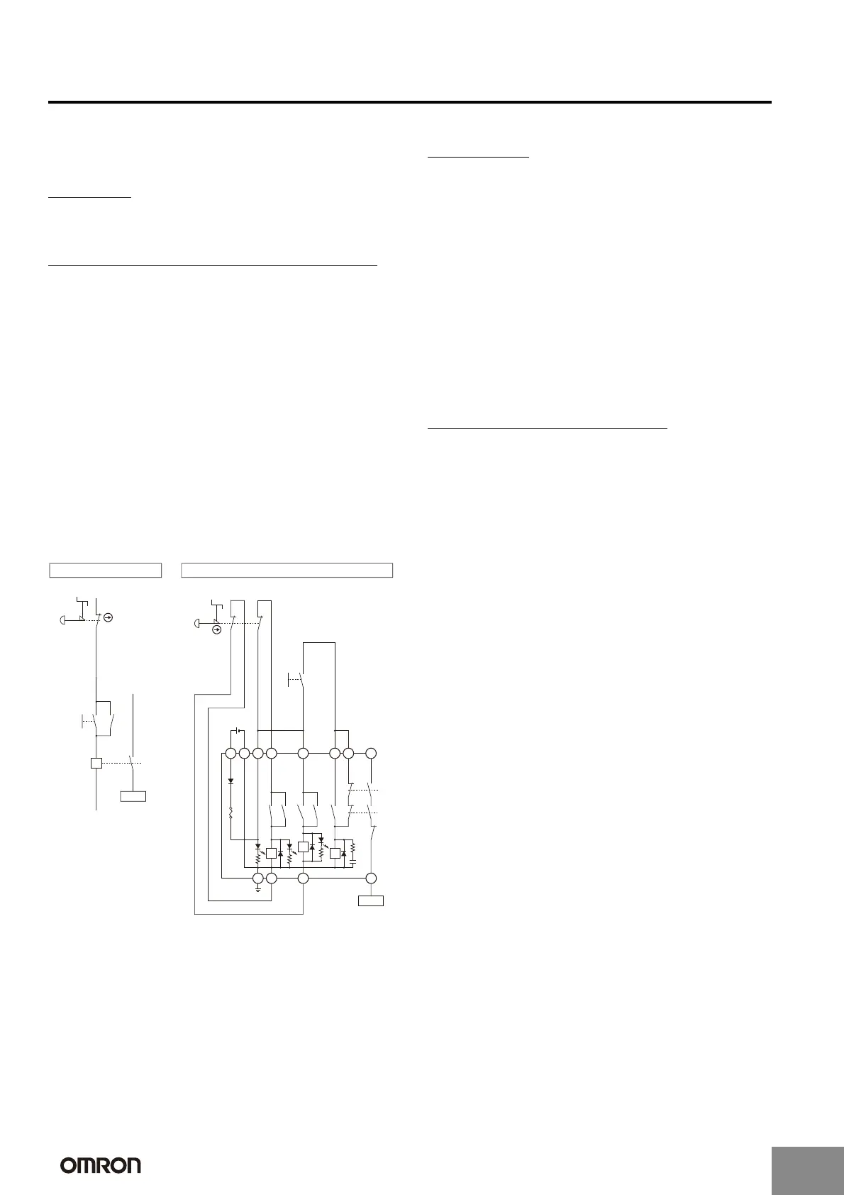
Relays with Forcibly Guided Contacts
While the Relay with Forcibly Guided Contacts has the previously
described forcibly guided contact structure, it is basically the same as
an ordinary relay in other respects. Rather than serving to prevent
malfunctions, the forcibly guided contact structure enables another
circuit to detect the condition following a contact weld or other
malfunction. Accordingly, when a contact weld occurs in a Relay with
Forcibly Guided Contacts, depending on the circuit configuration, the
power may not be interrupted, leaving the Relay in a potentially
dangerous condition (as shown in Fig. 1.)
To configure the power control circuit to interrupt the power when a
contact weld or other malfunction occurs, and to prevent restarting
until the problem has been eliminated, add another Relay with
Forcibly Guided Contacts or similar Relay in combination to provide
redundancy and a self-monitoring function to the circuit (as shown in
Fig. 2). Refer to the Technical Guide section.
The G9S/G9SA/G9SB Safety Relay Unit, which combines Relays
such as the Relay with Forcibly Guided Contacts in order to provide
the above-described functions, is available for this purpose. By
connecting a contactor with appropriate input and output to the
Safety Relay Unit, the circuit can be equipped with redundancy and a
self-monitoring function.
CE Marking
(Source: Guidelines on the Application of Council Directive 73/23/
EEC)
The G7SA, G7S and G7S-@-E have been recognized by the VDE for
meeting the Low Voltage Directive according to EN requirements for
relays and relays with forcibly guided contacts. The Low Voltage
Directive, however, contains no clauses that specify handling
methods for components, and interpretations vary among test sites
and manufacturers. To solve this problem, the European Commission
has created guidelines for the application of the Low Voltage
Directive in EU. These guidelines present concepts for applying the
Low Voltage Directive to components. The G7SA, G7S and G7S-@-
E, however, do not display the CE Marking according to the concepts
in the guidelines.
VDE recognition, however, has been obtained, so there should be no
problems in obtaining the CE Marking for machines that use the
G7SA, G7S or G7S-@-E. Use the manufacturer’s compliance
declaration to prove standard conformance.
Contents of the Guidelines
The Guidelines on the Application of Council Directive 73/23/EEC
apply to components. Relays with PWB terminals are not covered by
the Low Voltage Directive.
K1
S1
S2
K1
K1
S1
11
12
21
22
S2
K1
K2
K3
+ −
D
F1
K3 K1
K1 K1
K3 K2
K2 K2
K3
A1
A2
T11
T12
Y1 X1 13B1
PE
T21 T22
14
Fig 1 Fig 2
Power source
Power source
http://www.ia.omron.com/
C-1
(c)Copyright OMRON Corporation 2007 All Rights Reserved.
Artisan Technology Group - Quality Instrumentation ... Guaranteed | (888) 88-SOURCE | www.artisantg.com
 Loading...


