G-112 Safety Sensors / Components
Application Examples
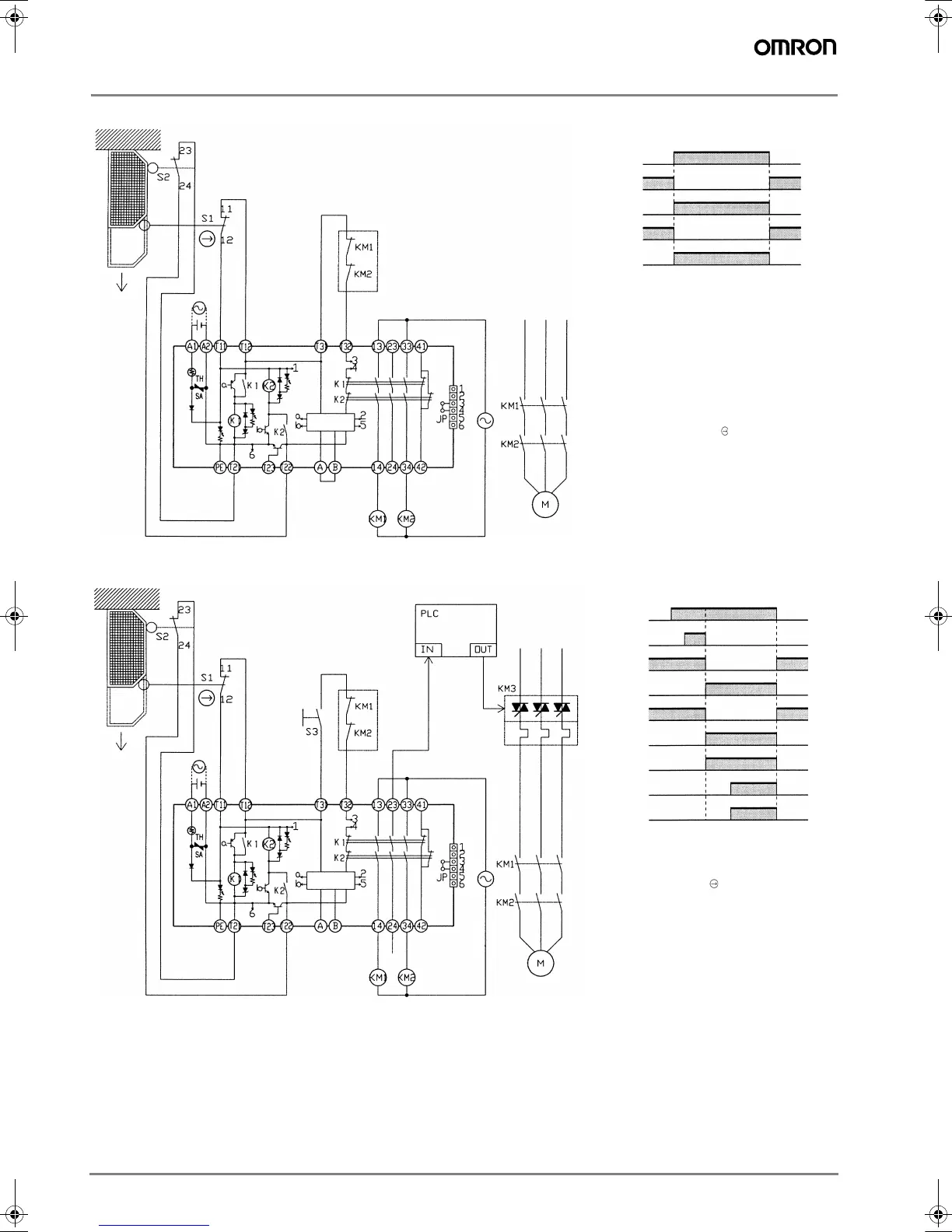
G9SA-301 (24 VAC/VDC) with 2-channel Limit Switch Input/Auto-reset
G9SA-301 (24 VAC/VDC) with 2-channel Limit Switch Input/Manual-reset
Feedback loop
Timing Chart
Open
Control
circuit
Limit switches
S1 and S2
K1 and K2
(NC)
K1 and K2
(NO)
KM1 and KM2
(NC)
KM1 and KM2
(NO)
S1: Safety Limit Switch
with direct opening mechanism
(D4N or D4B)
S2: Limit switch
KM1 and KM2: Magnetic Contactor
M: 3-phase motor
Note: This circuit achieves EN954-1
Safety Category 4.
Feedback loop
Timing Chart
PC input
PC output
KM3
Open
Control
circuit
Limit switches
S1 and S2
Reset switch
S3
K1 and K2
(NC)
K1 and K2
(NO)
KM1 and KM2
(NC)
KM1 and KM2
(NO)
S1: Safety Limit Switch
with direct opening mechanism
(D4N or D4B)
S2: Limit switch
S3: Reset switch
KM1 and KM2: Magnetic Contactor
KM3: Solid-state Contactor
M: 3-phase motor
Note: This circuit achieves EN954-1
Safety Category 4.
F502-EN2-04.book Seite 112 Dienstag, 26. Juli 2005 5:48 17

 Loading...


