H3CR-A
H3CR-A
13
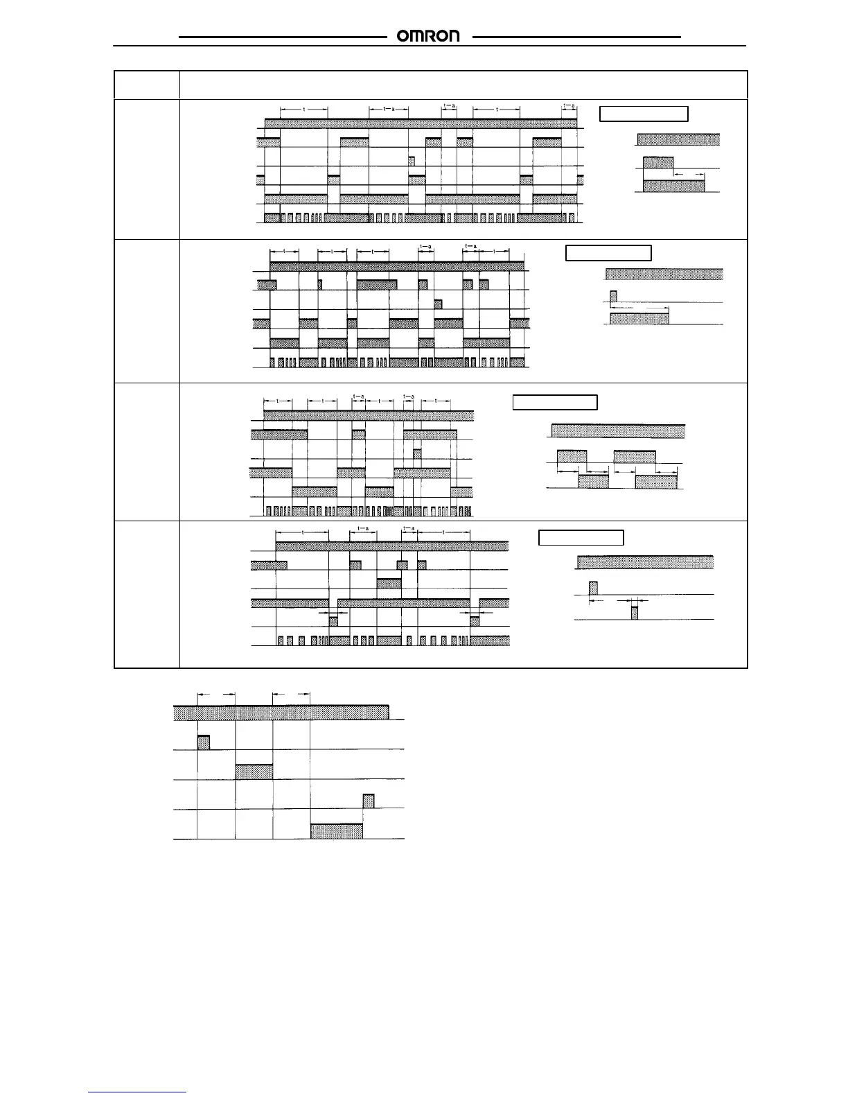
Operating
mode
Timing
chart
D:
Signal
OFF-delay
Basic operation
Power
Output
t
Output relay (NC)
Power indicator
Power
Start
Reset
Output relay (NO)
(Output indicator)
Note: Start input is valid and
re-triggerable
while the
Timer
is in operation.
Start
(see note)
E:
Interval
Power
Output
t
Basic operation
Power
Start
Reset
Output relay (NC)
Power indicator
Output relay (NO)
(Output indicator)
Note: Start input is valid and
re-triggerable while
the Timer is in opera-
tion.
Start
(see note)
G:
Signal
ON/OFF-
delay
Basic
operation
Power
Start
Reset
Output relay (NC)
Power indicator
Power
Output
t
t
Output relay (NO)
(Output indicator)
Note: Start input is valid and re-trigger-
able
while
the T
imer is in operation.
t
t
Start
(see note)
J:
One-shot
output
Basic
operation
Power
Start
Reset
Output relay (NC)
Power indicator
1±0.6 s
(Fixed)
1±0.6 s
(Fixed)
Output
Power
Output relay (NO)
(Output indicator)
1±0.6 s
(Fixed)
Note: Start input is valid and re-
triggerable while the Timer
is
in operation.
Start
(see note)
t
Gate
Signal Input
Power
Start
Gate
Reset
Output
relay
ON
OFF
ON
OFF
ON
OFF
ON
OFF
ON
OFF
Note: 1. This
timing chart indicates
the gate input in op
-
erating
mode A (ON-delay operation).
2.
The set time is the sum of t
1
and t
2
.
3.
H3CR-AP model incorporates start input only
.
t
1
t
2
 Loading...