H3CR-A
H3CR-A
9
Engineering Data
Reference:A
maximum current of 0.15 A can be switched at 125 VDC (cos
φ
= 1)
and a maximum current of 0.1 A can be switched if L/R is 7 ms. In
both cases, a life of 100,000 operations can be expected.
The minimum applicable load is 10 mA (100 mA for H3CR-A8E) at
5 VDC (failure level: P).
Load current (A)
30 VDC L/R = 7 ms
250 VAC/30 VDC
(cosφ
= 1)
250 VAC (cosφ
= 0.4)
Switching operations (x 10 )
3
10,000
5,000
1,000
500
100
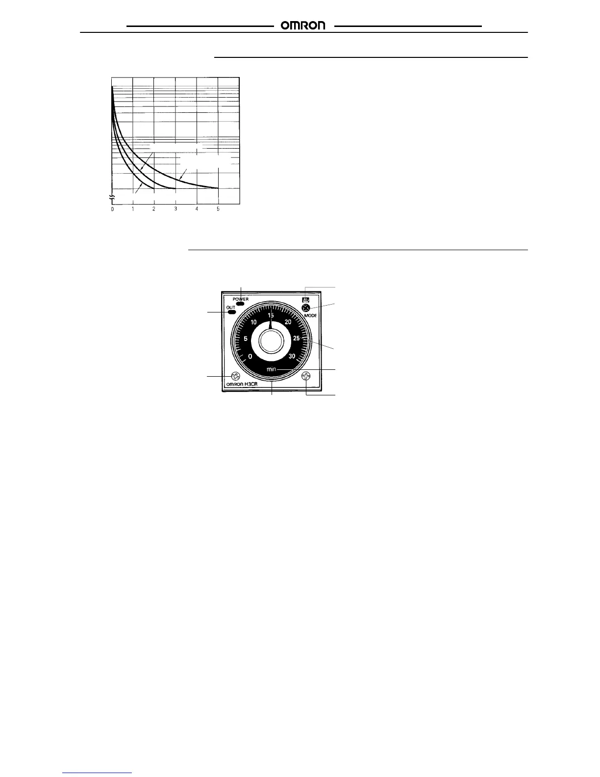
Nomenclature
Power
indicator (green) (Flashes when T
imer
operates; lit when T
imer stops operating)
Operating mode display window
Operating mode selector
Select a mode from:
A, B, B2, C, D, and E (H3CR-A, -AP
, and -AS)
A, B2, E and J (H3CR-A8, -A8S, and -A8E)
G and J (H3CR-A-300)
Scale range display windows
T
ime unit display window
T
ime unit selector (select one
from sec, min, hrs, and 10h)
T
ime setting
knob (set time)
Output indicator (orange)
(Lit when output)
T
ime range selector (select one
from 1.2, 3, 12, and 30 at full
scale; with the H3CR-Aj-301,
select from 2.4, 6, 24, or 60 at
full scale. )

 Loading...