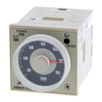
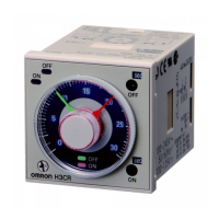
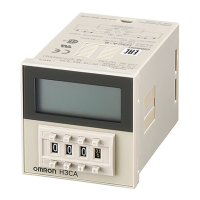
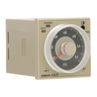
H3CR-F
H3CR-F
25
Ratings
Rated
supply voltage (see note)
100 to 240 V
AC (50/60 Hz),12 VDC, 24 VAC/DC (50/60 Hz), 48 to 125 VDC
Operating voltage range
85% to 1
10% of rated supply voltage; 90% to 1
10% with 12-VDC models
Power reset
Minimum power-opening time: 0.1 s
Power consumption
100 to 240 V
AC:
approx. 10 V
A (2.1 W) at 240 V
AC
24 V
AC/VDC:
approx. 2 V
A (1.7 W) at 24 V
AC
approx. 1 W at 24 VDC
48 to 125 VDC:
approx. 1.5 W at 125 VDC
12 VDC:
approx. 1 W at 12 VDC
Control outputs
Contact output: 5 A at 250 V
AC/30 VDC, resistive load (cosφ
= 1)
Note: A
power supply with a ripple of 20% max. (single-phase power supply with full-wave rectification) can be used with each DC Model.
Characteristics
Accuracy
of operating
time
±
0.2% FS max. (
±
0.2% FS
±
10 ms max. in ranges of 1.2 and 3 s)
Setting error ±
5% FS
±
50 ms max.
Reset time
0.1 s max.
Reset voltage
10 % max. of rated voltage
Influence of voltage
±
0.2% FS max. (
±
0.2% FS
±
10 ms max. in ranges of 1.2 and 3 s)
Influence of
temperature
±
1% FS max. (
±
1% FS
±
10 ms max. in ranges of 1.2 and 3s)
Insulation resistance
100 M
Ω
min. (at 500 VDC)
Dielectric strength
2,000 V
AC, 50/60 Hz for 1 min (between current-carrying metal parts and exposed non-current-carrying
metal parts)
2,000 V
AC, 50/60 Hz for 1 min (between control output terminals and operating circuit)
2,000 V
AC, 50/60 Hz for 1 min (between contacts of dif
ferent polarities)
1,000 V
AC, 50/60 Hz for 1 min (between contacts not located next to each other)
Impulse withstand
voltage
3 kV (between power terminals) for 100 to 240 V
AC, 48 to 125 VDC
1 kV for 12 VDC, 24 V
AC/DC
4.5 kV (between current-carrying terminal and exposed non-current-carrying metal parts) for 100 to 240 V
AC,
48 to 125 VDC
1.5 kV for 12 VDC, 24 V
AC/DC
Noise immunity
±
1.5 kV (between power terminals), square-wave noise by noise simulator (pulse width: 100 ns/1
µs, 1-ns
rise)
±
400 V for 12 VDC
Static immunity
Malfunction:8 kV
Destruction: 15 kV
V
ibration resistance
Destruction:
10 to 55 Hz with 0.75-mm single amplitude for 2 hrs each in three directions
Malfunction:
10 to 55 Hz with 0.5-mm single amplitude for 10 min each in three directions
Shock resistance
Destruction:
980 m/s
2
three times each in six directions
Malfunction:
98 m/s
2
three times each in six directions
Ambient temperature
Operating:–10°
C to 55
°
C (with no icing)
Storage: –25°
C to 65
°
C (with no icing)
Ambient humidity
Operating: 35% to 85%
Life expectancy
Mechanical:
20 million operations min. (under no load at 1,800 operations/h)
Electrical:
100,000 operations min. (5 A at 250 V
AC, resistive load at 1,800 operations/h)
EMC (EMI) EN50081-2
Emission Enclosure: EN55011 Group 1 class A
Emission AC Mains:
EN55011 Group 1 class A
(EMS) EN50082-2
Immunity ESD:
EN61000-4-2:
4 kV contact discharge (level 2)
8 kV air discharge (level 3)
Immunity RF-interference from AM Radio W
aves: ENV50140:
10 V/m (80 MHz to 1 GHz)
(level 3)
Immunity RF-interference from Pulse-modulated Radio W
aves: ENV50204:
10 V/m (900
±
5 MHz) (level 3)
Immunity Conducted Disturbance:
ENV50141:
10 V (0.15 to 80 MHz) (level 3)
Immunity Burst:
EN61000-4-4:
2 kV power-line (level 3)
2 kV I/O signal-line (level 4)
Immunity Surge:
EN61000-4-5:
1 kV line to line (level 3)
2 kV line to ground (level 3)
Case color
Light Gray (Munsell 5Y7/1)
Enclosure ratings
IP40 (panel surface)
Weight
Approx. 100 g


 To Next Page