26 Solid-state Twin Timers H3CR-F
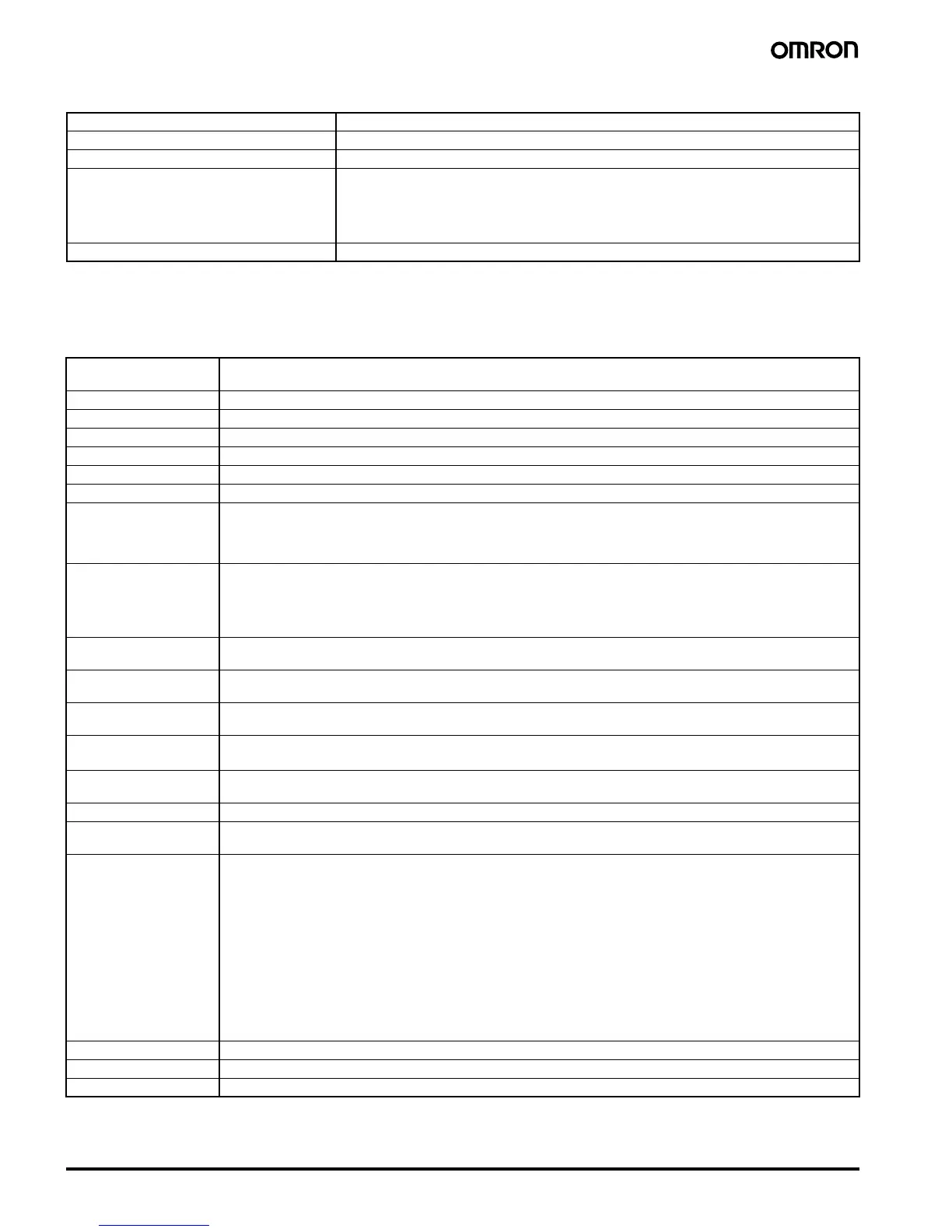
■ Ratings
Note: 1. A power supply with a ripple of 20% max. (single-phase power supply with full-wave rectification) can be used with each DC Model.
2. Do not use an inverter output as the power supply. Refer to Power Supplies in Safety Precautions for All Timers on page 51 for details.
3. Refer to Power Supplies in Safety Precautions for All Timers on page 51 when using the Timer together with a 2-wire AC proximity sensor.
■ Characteristics
Note: Refer to the Life-test Curve.
Rated supply voltage (See notes 1, 2, and 3.) 100 to 240 VAC (50/60 Hz),12 VDC, 24 VAC/DC (50/60 Hz), 48 to 125 VDC
Operating voltage range 85% to 110% of rated supply voltage; 90% to 110% with 12-VDC models
Power reset Minimum power-opening time: 0.1 s
Power consumption 100 to 240 VAC: approx. 10 VA (2.1 W) at 240 VAC
24 VAC/VDC: approx. 2 VA (1.7 W) at 24 VAC
approx. 1 W at 24 VDC
48 to 125 VDC: approx. 1.5 W at 125 VDC
12 VDC: approx. 1 W at 12 VDC
Control outputs Contact output: 5 A at 250 VAC/30 VDC, resistive load (cos
φ = 1)
Accuracy of operating
time
±0.2% FS max. (±0.2% FS ±10 ms max. in ranges of 1.2 and 3 s)
Setting error
±5% FS ±50 ms max.
Reset time 0.1 s max.
Reset voltage 10% max. of rated voltage
Influence of voltage
±0.2% FS max. (±0.2% FS ±10 ms max. in ranges of 1.2 and 3 s)
Influence of temperature
±1% FS max. (±1% FS ±10 ms max. in ranges of 1.2 and 3s)
Insulation resistance 100 M
Ω min. (at 500 VDC)
Dielectric strength 2,000 VAC, 50/60 Hz for 1 min (between current-carrying metal parts and exposed non-current-carrying metal parts)
2,000 VAC, 50/60 Hz for 1 min (between control output terminals and operating circuit)
2,000 VAC, 50/60 Hz for 1 min (between contacts of different polarities)
1,000 VAC, 50/60 Hz for 1 min (between contacts not located next to each other)
Impulse withstand volt-
age
3 kV (between power terminals) for 100 to 240 VAC, 48 to 125 VDC
1 kV for 12 VDC, 24 VAC/DC
4.5 kV (between current-carrying terminal and exposed non-current-carrying metal parts) for 100 to 240 VAC, 48 to
125 VDC
1.5 kV for 12 VDC, 24 VAC/DC
Noise immunity
±1.5 kV (between power terminals), square-wave noise by noise simulator (pulse width: 100 ns/1 µs, 1-ns rise)
±400 V for 12 VDC
Static immunity Malfunction: 8 kV
Destruction: 15 kV
Vibration resistance Destruction: 10 to 55 Hz with 0.75-mm single amplitude for 2 hrs each in three directions
Malfunction: 10 to 55 Hz with 0.5-mm single amplitude for 10 min each in three directions
Shock resistance
Destruction: 980 m/s
2
three times each in six directions
Malfunction: 98 m/s
2
three times each in six directions
Ambient temperature Operating:
−10°C to 55°C (with no icing)
Storage:
−25°C to 65°C (with no icing)
Ambient humidity Operating: 35% to 85%
Life expectancy Mechanical: 20 million operations min. (under no load at 1,800 operations/h)
Electrical: 100,000 operations min. (5 A at 250 VAC, resistive load at 1,800 operations/h) (See note)
EMC (EMI) EN61812-1
Emission Enclosure: EN55011 Group 1 class A
Emission AC Mains: EN55011 Group 1 class A
(EMS) EN61812-1
Immunity ESD: IEC61000-4-2: 6 kV contact discharge (level 3)
8 kV air discharge (level 3)
Immunity RF-interference from AM Radio Waves: IEC61000-4-3: 10 V/m (80 MHz to 1 GHz) (level 3)
Immunity RF-interference from Pulse-modulated Radio Waves: IEC61000-4-3: 10 V/m (900
±5 MHz) (level 3)
Immunity Conducted Disturbance: IEC61000-4-6: 10 V (0.15 to 80 MHz) (level 3)
Immunity Burst: IEC61000-4-4: 2 kV power-line (level 3)
2 kV I/O signal-line (level 4)
Immunity Surge: IEC61000-4-5: 1 kV line to line (level 3)
2 kV line to ground (level 3)
Case color Light Gray (Munsell 5Y7/1)
Degree of protection IP40 (panel surface)
Weight Approx. 100 g