Solid-state Twin Timers H3CR-F 27
■ Life-test Curve
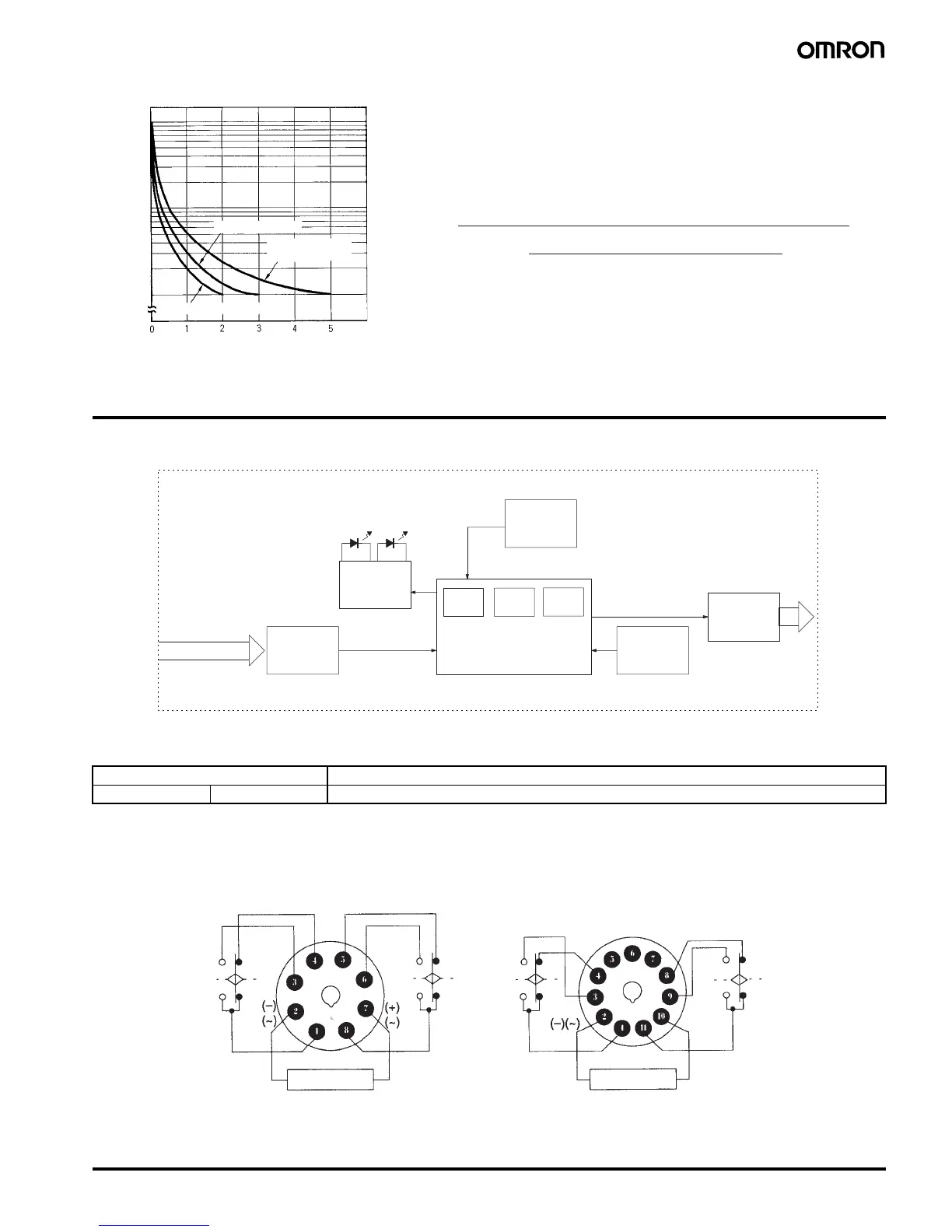
Connections
■ Block Diagrams
■ I/O Functions
■ Terminal Arrangement
10,000
5,000
1,000
500
100
Load current (A)
30 VDC L/R = 7 ms
250 VAC (cosφ = 0.4)
Switching operations (x 10
3
)
250 VAC/30 VDC
(cosφ = 1)
Reference: A maximum current of 0.15 A can be switched at 125 VDC (cosφ = 1)
and a maximum current of 0.1 A can be switched if L/R is 7 ms. In
both cases, a life of 100,000 operations can be expected.
The minimum applicable load is 10 mA at 5 VDC (failure level: P).
ON indicator OFF indicator
One-chip microcomputer
ROM
RAM
Clock
AC (DC) input
Power supply
circuit
Indicator
circuit
Zero setting
detection
circuit
Time range/unit
selectors
Output
circuit
Inputs ---
Outputs Control output Outputs are turned ON/OFF according to the time set by the ON- and OFF-time setting knob.
(+)(~)
Power supply
Power supply
H3CR-F8
H3CR-F8
NH3CR-F8-300
H3CR-F8N-300
H3CR-F
H3CR-FN
H3CR-F-300
H3CR-FN-300
Note: Leave terminals 5, 6, and 7 open.
Do not use them as relay terminals.