H5CZ
4
• Up/Down Keys for each digit enable easy operation.
• Cyclic control is easy with the Twin Timer and Variable ON/OFF Duty modes.
Specifications
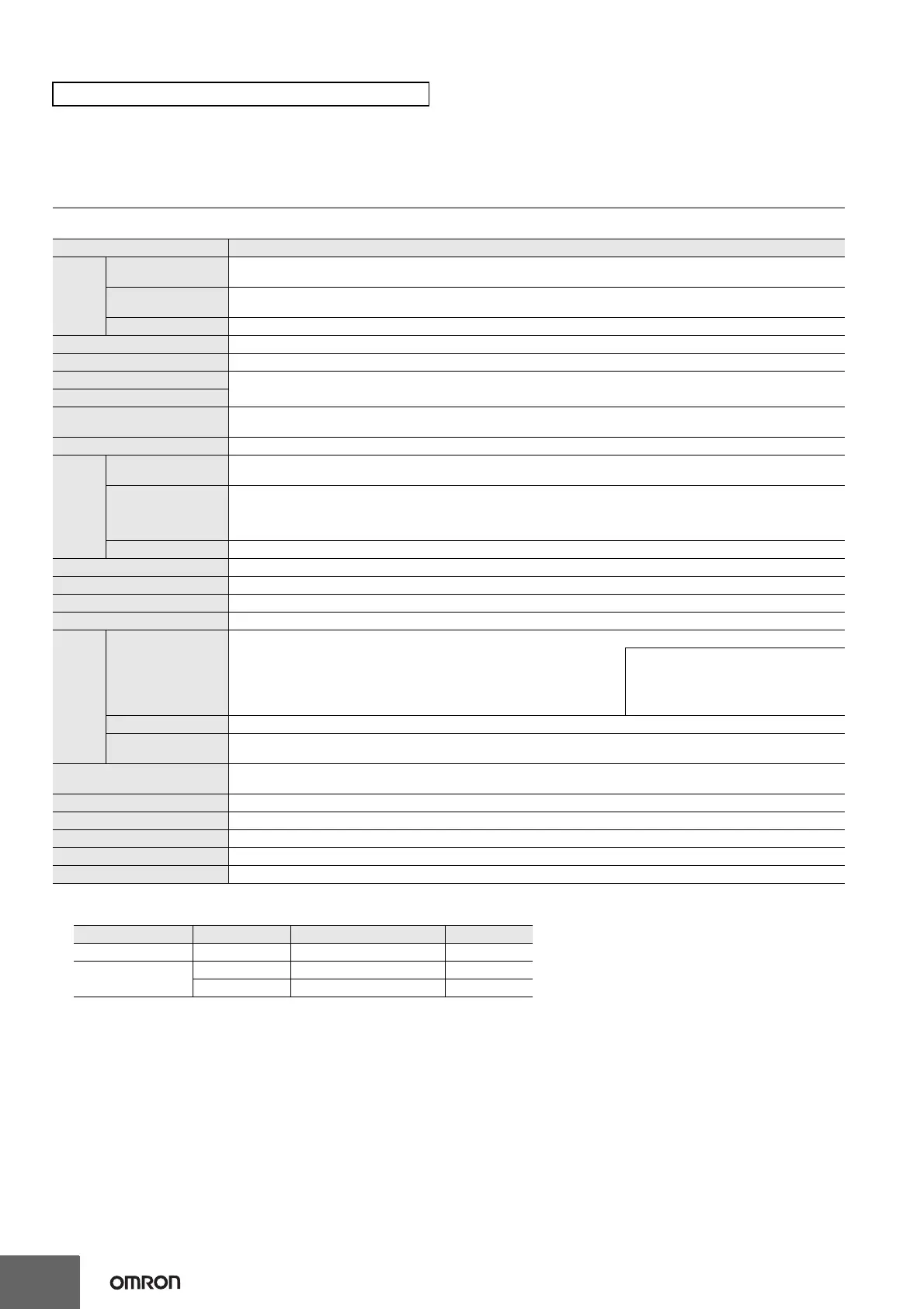
Ratings
*1. Do not use the output from an inverter as the power supply. The ripple must be 20% maximum for DC power.
*2. Inrush current will flow for a short time when the power supply is turned ON.
Inrush Current (Reference Values)
*3. The display is lit only when the power is ON. Nothing is displayed when power is OFF.
H5CZ Digital Timers
Item Models H5CZ-L8@
Ratings
Power supply
voltage
*1
• 100 to 240 VAC 50/60 Hz
• 12 to 24 VDC/24 VAC 50/60 Hz
Operating voltage
fluctuation range
85% to 110% of rated supply voltage (90% to 110% at 12 to 24 VDC)
Power consumption Approx. 6.2 VA at 100 to 240 VAC, Approx. 5.1 VA/2.4 W at 24 VAC/12 to 24 VDC
*2
Mounting method Flush mounting, Surface mounting, DIN track mounting
External connections 8-pin socket
Degree of protection
IEC IP66, UL508 Type 4X (indoors) for panel surface only and when Y92S-29 Waterproof Packing is used
4 digits
Digits
Time ranges
0.001 s to 9.999 s, 0.01 s to 99.99 s, 0.1 s to 999.9 s, 1 s to 9999 s, 1 s to 99 min 59 s
0.1 m to 999.9 min, 1 min to 9999 min, 1 min to 99 h 59 min, 0.1 h to 999.9 h, 1 h to 9999 h
Timer mode Elapsed time (Up), Remaining time (Down) (selectable)
Inputs
Input signals
Signal, Reset
(no inputs on models with instantaneous contact outputs)
Input method
No-voltage Input
ON impedance: 1 kΩ max. (Leakage current: 12 mA when 0 Ω)
ON residual voltage: 3 V max.
OFF impedance: 100 kΩ min.
Signal, reset Minimum input signal width: 1 or 20 ms (selectable, same for all input)
Reset system Power reset (depending on output mode), External reset, Manual reset, Automatic reset (depending on output mode)
Power reset Minimum power-opening time: 0.5 s (except for A-3, b-1, F, ton-1, and toff-1 mode)
Reset voltage 10% max. of rated supply voltage
Sensor waiting time 250 ms max. (Control output is turned OFF and no input is accepted during sensor waiting time.)
Output
Output modes
A: Signal ON Delay I, A-1: Signal ON Delay II, A-2: Power ON Delay I, A-3: Power
ON Delay II, b: Repeat Cycle 1, b-1: Repeat Cycle 2, d: Signal OFF Delay, E:
Interval, F: Cumulative, Z: ON/OFF-duty-adjustable flicker, S: Stopwatch, toff:
Flicker OFF Start 1, ton: Flicker ON Start 1, toff-1: Flicker OFF Start 2, ton-1:
Flicker ON Start 2
Models with Instantaneous Contact Outputs
A-2: Power ON Delay I, b: Repeat Cycle 1,
E: Interval, Z: ON/OFF-duty-adjustable
flicker, toff: Flicker OFF Start 1, ton: Flicker
ON Start 1
One-shot output time 0.01 to 99.99 s
Control output
5 A at 250 VAC/30 VDC, resistive load (cos =1)
Minimum applied load: 10 mA at 5 VDC (failure level: P, reference value)
Display method
*3
LCD; Present value: 10-mm-high characters
Set value: 6-mm-high characters
Memory backup EEPROM (overwrites: 100,000 times min.) that can store data for 10 years min.
Operating temperature range -10 to 55°C (-10 to 50°C if counters are mounted side by side) (with no icing or condensation)
Storage temperature range -25 to 70°C (with no icing or condensation)
Operating humidity range 25% to 85%
Front panel color Light gray (5Y7/1)
Voltage Applied voltage Inrush current (peak value) Time
100 to 240 VAC 264 VAC 5.3 A 0.4 ms
12 to 24 VDC/24 VAC
26.4 VAC 6.4 A 1.4 ms
26.4 VDC 4.4 A 1.7 ms