H5CZ
6
Connections
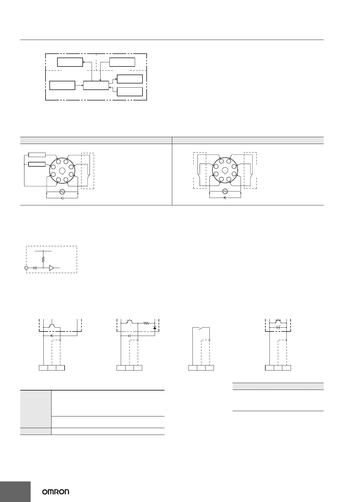
Block Diagram
Note: Basic insulation is provided between the power supply circuit and the input circuits. However, basic insulation is not provided in the
H5CZ-@D.
Terminal Arrangement
Confirm that the power supply meets specifications before use.
Note: Do not connect unused terminals as relay terminals.
Input Circuits
Signal and Reset Input
Input Connections
The inputs are no-voltage (closed or open). (The H5CZ-L8E@ does not have an input.)
No-voltage Inputs (NPN Inputs)
H5CZ-L8/-L8D H5CZ-L8E/-L8ED
Open Collector Voltage Output Contact Input DC Two-wire Sensor
Output circuit
(See note.)
Internal control
circuit
Display circuit
Key switch circuit
Input circuits
Power supply
circuit
(Basic insulation)
(Basic insulation)
4
3
2
1 8
7
6
5
0V
Signal
Reset
Internal circuit
Contact
output
(-) (+)
Terminals 1 and 2 of the H5CZ-L8D
are connected internally.
4
3
2
1 8
7
6
5
(–) (+)
Internal circuit Internal circuit
Instantaneous
contact output
OUT1
Time-limit
contact output
OUT2
Internal
circuit
IN
+14 V
1 kΩ
No-voltage Inputs (NPN Inputs)
134
PLC or
sensor
Note: Operate with transistor ON
0 V for inputs
Reset input
Signal input
Sensor
0 V for inputs
Reset input
Signal input
134
Note: Operate with transistor ON
Note: Operate with relay ON
0 V for inputs
Reset input
Signal input
134
Note: Operate with transistor ON
0 V for inputs
Reset input
Signal input
134
Applicable Two-wire Sensor
• Leakage current: 1.5 mA max.
• Switching capacity: 5 mA min.
• Residual voltage: 3.0 VDC max.
• Operating voltage: 10 VDC
No-voltage Input Signal Levels
Note: The DC voltage must be 30 VDC max.
No-contact
input
Short-circuit level Transistor ON
• Residual voltage: 3 V max.
• Impedance when ON: 1 kΩ max.
(The leakage current is approx. 12 mA when the
impedance is 0 Ω.)
Open level Transistor OFF
• Impedance when OFF: 100 kΩ min.
Contact input Use contacts which can adequately switch 5 mA at 10 V