38
H7CX-R@-N
Characteristics
I/O Functions
* Refer to page page 50 for details on the hold function.
• The following table shows the delay from when the reset signal is
input until the output is turned OFF. (Reference values)
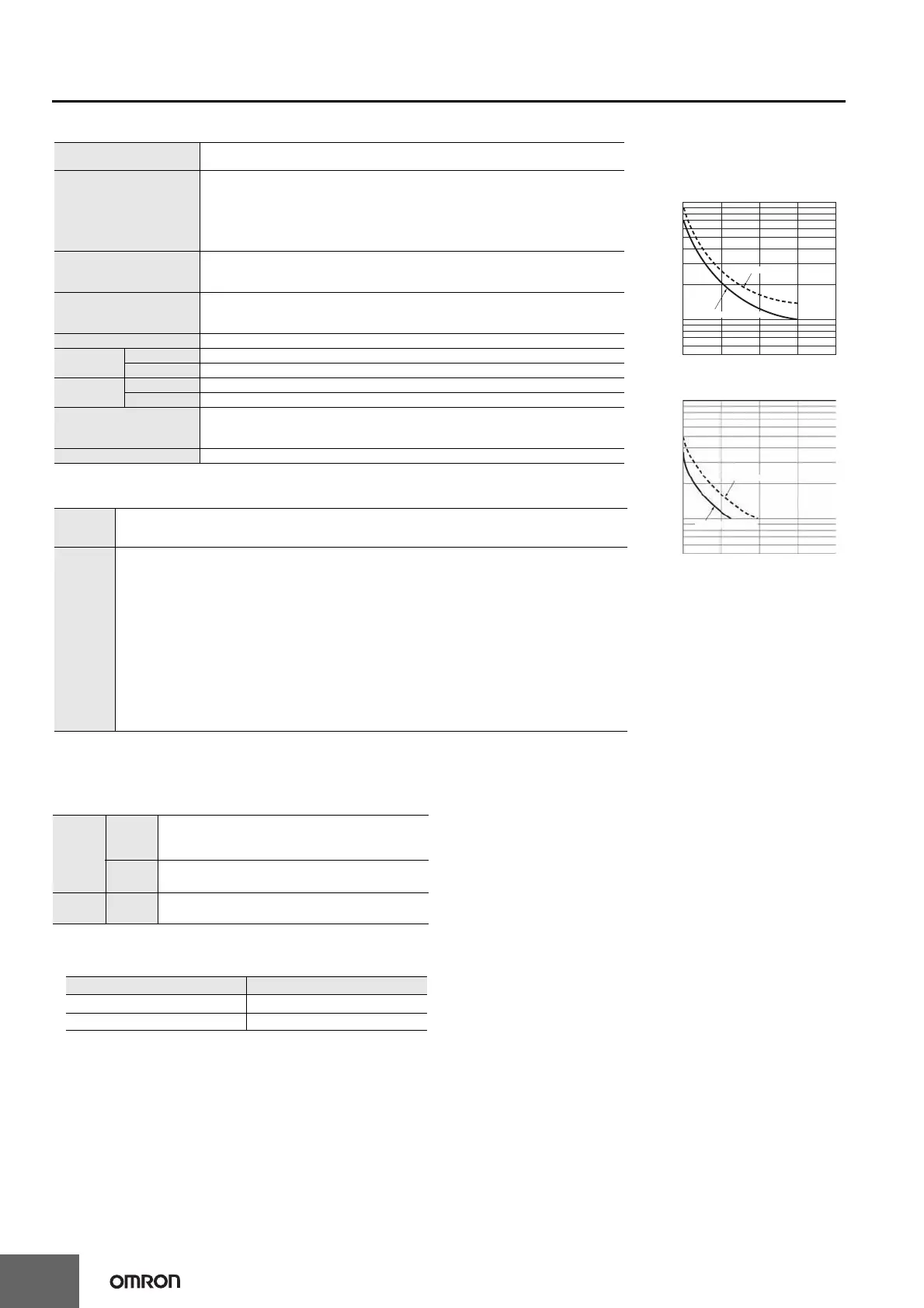
*See Life-test Curve (Reference Values) on the right.
Applicable Standards
* The following safety standards apply to the H7CX-R11@.
cUL (Listing): Applicable when an OMRON P2CF(-E) Socket is used.
cUR (Recognition): Applicable when any other socket is used.
Insulation resistance
100 MΩ min. (at 500 VDC) between current-carrying terminal and exposed non-
current-carrying metal parts, and between non-continuous contacts
Dielectric strength
2,000 VAC, 50/60 Hz for 1 min between current-carrying metal parts and non-current-
carrying metal parts
2,000 VAC (for 100 to 240 VAC), 50/60 Hz for 1 min between power supply and input
circuit (1,000 VAC for 24 VAC/12 to 24 VDC)
2,000 VAC 50/60 Hz for 1 min between control output, power supply, and input circuit
1,000 VAC, 50/60 Hz for 1 min between non-continuous contacts
Impulse withstand voltage
3.0 kV (between power terminals) for 100 to 240 VAC, 1.0 kV for 24 VAC/12 to 24 VDC
4.5 kV (between current-carrying terminal and exposed non-current-carrying metal
parts) for 100 to 240 VAC, 1.5 kV for 24 VAC/12 to 24 VDC
Noise immunity
±1.5 kV (between power terminals)
±600 V (between input terminals)
Square-wave noise by noise simulator (pulse width: 100 ns/1 µs, 1-ns rise)
Static immunity Destruction: 15 kV, Malfunction: 8 kV
Vibration
resistance
Destruction 10 to 55 Hz with 0.75-mm single amplitude, each in three directions for 2 hours
Malfunction 10 to 55 Hz with 0.35-mm single amplitude, each in three directions for 10 min
Shock re-
sistance
Destruction 300m/s
2
each in three directions, three cycles
Malfunction 100m/s
2
each in three directions, three cycles
Life expectancy
Mechanical: 10,000,000 operations min.
Electrical: 100,000 operations min. (3 A at 250 VAC, resistive load, ambient
temperature condition: 23°C) *
Weight Approx. 110 g (Tachometer only)
Approved
safety
standards
cULus (or cURus): UL508/CSA C22.2 No. 14*
Conforms to EN 61010-1 (IEC 61010-1): Pollution degree 2/overvoltage category II, B300 PILOT DUTY,
1/4 HP 120 VAC, 1/3 HP, 240 VAC, 3-A resistive load
EMC
(EMI)
Emission Enclosure:
Emission AC mains:
(EMS)
Immunity ESD:
Immunity RF-interference:
Immunity Conducted Disturbance:
Immunity Burst:
Immunity Surge:
Immunity Voltage Dip/Interruption:
EN61326
EN55011 Group 1 classA
EN55011 Group 1 classA
EN61326
EN61000-4-2: 4 kV contact discharge (level 2);
8 kV air discharge (level 3)
EN61000-4-3: 10 V/m (Amplitude-modulated, 80 MHz to 1 GHz)
(level 3);
10 V/m (Pulse-modulated, 900 MHz ±5 MHz) (level 3)
EN61000-4-6: 10 V (0.15 to 80 MHz) (level 3)
EN61000-4-4: 2 kV power-line (level 3);
1 kV I/O signal-line (level 4)
EN61000-4-5: 1 kV line to lines (power and output lines) (level 2);
2 kV line to ground (power and output lines) (level 3)
EN61000-4-11: 0.5 cycle, 100% (rated voltage)
Life-test Curve
(Reference Values)
Resistive Load
Inductive Load
A current of 0.15 A max. can be switched at
125 VDC (cosφ=1) (Life expectancy: 100,000
operations)
A current of 0.1 A max. can be switched if
L/R=7 ms.
(Life expectancy: 100,000 operations)
1,000
700
500
300
100
70
50
Load current (A)
01 2 34
30 VDC (cosφ=1)
250 VAC (cosφ=1)
No. of operations (
×
10
3
)
1,000
700
500
300
100
70
50
01 2 34
30 VDC (L/R=7 ms)
Load current (A)
250 VAC (cosφ=1)
No. of operations (
×
10
3
)
Inputs
Count,
count 1,
count 2
Reads counting signals.
Hold
• Holds the measurement value and outputs.
• The hold indicator is lit during hold.*
Outputs OUT
Outputs signals according to the specified output
mode when a comparison value is reached.
Minimum reset signal width Output delay time
1 ms 0.8 to 1.2 ms
20 ms 15 to 25 ms

 Loading...


