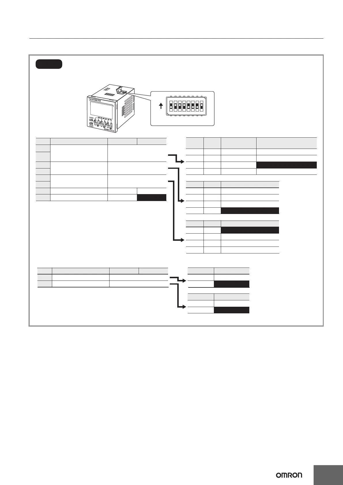
Refer to the following for the detailed procedure.
• DIP switch settings are effective when the power is turned ON again. (Perform DIP switch settings while the power is OFF.)
The settings made using the DIP switch can be checked in the
DIP switch monitor mode.
OFF
ON
OFF
ON
OFF
OFF
ON
ON
Tachometer
AMD compatible
Tachometer
AMD compatible
Input mode
*1
Counting speed/
Minimum input signal width
Output mode
*2
Average processing
---
NPN/PNP input mode
--- ---
NPN PNP
30 Hz
10 ms
10 kHz
*3
1 ms
OFF
ON
OFF
ON
OFF
OFF
ON
ON
Upper and lower limit
Area
Upper limit
Lower limit
OFF
ON
OFF
ON
OFF
OFF
ON
ON
OFF (no average processing)
2 times
4 times
8 times
Step1
Upper limit
Upper limit
Item OFF ON
Counting speed/
minimum input signal width
Input mode Pin 2 Pin 1
Output mode Pin 4 Pin 6
Average processing Pin 6 Pin 5
1
2
3
4
5
6
7
8
Set the basic parameters.
Refer to the table on the right.
Note: The characters displayed in reverse video are the default settings.
Refer to the table on the right.
Refer to the table on the right.
*1. The setting of Pin 1 is disabled (OFF) for the H7CX-R11W@.
*2. For the H7CX-R11W@.
Refer to the table on the right.
Refer to the table on the right.
Output 1 mode
Output 2 mode
Note: The characters displayed in reverse video are the default settings.
OFF
ON
OFF
ON
3
4
Item OFF ON
Output mode Pin 4
Output mode
Pin 3
Lower limit
Lower limit
*3. For the H7CX-R11W@, the counting speed will be 5 kHz even if 10 kHz
is selected.
OFF
ON
1 2 3 4 5 6 7 8
(Factory setting)

 Loading...


