11
H8CA-SH8CA-S
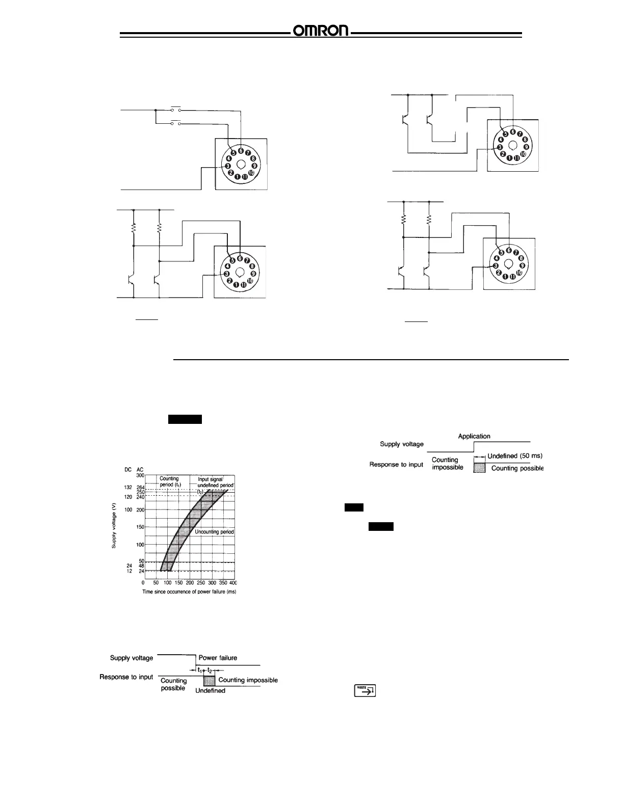
Input 1
(+)
Input 2
(A count signal is input
when turned ON.)
(–)
E (30 VDC max.)*
(+)
R
R
Input 1
Input 2
(A count signal
is input when
turned OFF.)
(V) 5 V
*At ``High'' level
4.7E
4.7 + R
30 VDC max.
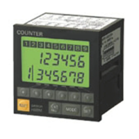
■ POWER FAILURE DETECTION
The H8CA-S is capable of detecting and indicating a power
failure on the display. Before power application or when a
power failure occurs, the “ PW OFF ” display flickers indicating
that the control power supply is off.
Relation among t
1
, t
2
, and supply voltage
Operations
Likewise, on power application, there is a period during which
the counter does not respond to the input signal, as shown
below because of a lag in the rise in the internal circuit voltage.
■ OPERATION AND DISPLAY
“ OUT ” is displayed when counting or timing is completed.
When “ MODE ” lights on display, terminals 1 and 3 are
connected. In this case, it is not possible to preset values. Be
sure to disconnect the terminals.
The H8CA-S uses “regular read format,” so the preset values
can be changed whether power is ON or OFF.
When changing the preset value during timer or counter
operation, a signal will be output when the new value is the
same as the displayed value.
The front panel keys operate at a touch. Do not press the keys
with excessive force or tools, such as a screwdriver. Press only
with fingers.
After presetting values, part of the display might be blinking.
The H8CA-S will operate normally in this condition, but press
the key so that characters do not blink.
(–)
*At ``High'' level
4.7E
4.7 + R
(V) 5 V
Input 2
Input 1
(A count signal
is input when
turned OFF.)
CONNECTION OF COUNT INPUTS (Continued)
Voltage Input type
When a power failure occurs, there is a period during which
the counter does not respond to the input signal, as shown
below, because of lag in the rise in the internal circuit voltage.
(–)
(+)
30 VDC max.
(A count
signal is
input when
turned ON.)
Input 2
Input 1
(–)
(+)
R
R