EasyManua.ls Logo

Omron H8BM Series

Omron H8BM Series
13 pages
To Next Page IconTo Next Page
Loading...
1
Multi-maintenance Counter H8BM
Nine Built-in Counters/Timers to
Measure Equipment Utilization
Up to nine Counters can be used as counters or
accumulative timers.
Can be used as a multi-stage preset counter.
Individual outputs to indicate maintenance timing.
Pre-forecast/Forecast and machine stoppage
output provided.
IP54F enclosure rating for resistance to oil and
water.
Compact, short-body: 72 x 72 x 79 mm (DIN).
Directly connectable to 2-wire DC sensors.
RC
Ordering Information
Number
of stages
Output Model
3-stage setting
NPN H8BM-B
3 s age se g
PNP H8BM-BP
1-stage setting
NPN H8BM-BD
s age se g
PNP H8BD-BDP
Accessories (Order Separately)
Replacement Parts
Name Model
Hard Protective Cover Y92A-72C
Rubber Packing
Y92S-25
A
Hard Protective Cover and Rubber Packing are
supplied with the
Counter.
Short
Bar
Short
Bar
Y92S-26
When the Counter is used as a multi-stage preset counter, wiring
will be facilitated if Counter inputs 1 through 9 are short-circuited
with
the following Short Bar
.
5-pole
4-pole
Both
the 5-pole and 4-pole Short Bars are used to short-circuit the 9
Counter
inputs.
Question and Answer IconNeed help?

Do you have a question about the Omron H8BM Series and is the answer not in the manual?

Omron H8BM Series Specifications

General IconGeneral
BrandOmron
ModelH8BM Series
CategoryCash Counter
LanguageEnglish

Summary

Nine Built-in CountersTimers to Measure Equipment Utilization

Ordering Information

Specifications

Ratings

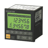
Electrical and operational ratings for the H8BM counter models.

IO Functions

Inputs

Details on the input signals and their functions for the H8BM counter.

Operation

Selecting CounterTimer Operation

Procedure for selecting between counter and timer operation using DIP switches.

Clearing Settings

Methods to clear all counter settings and count values.

Self-diagnostic Function

Displays and recovery procedures for errors.

Installation

Terminal Arrangement

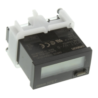
Diagram showing the layout and numbering of all terminals.

Connections

PNP Output

Input Connections (Solid-state Switches)

Precautions

Power Supply

Information on power supply insulation and unstable periods during power cycling.

Related product manuals