H8BM
H8BM
3
Characteristics
Insulation
resistance
100 M
Ω
min. (at 250 VDC) (between current-carrying terminals and exposed non-current-carrying
metal parts)
Dielectric strength
1,000 V
AC, 50/60 Hz for 1 min (between current-carrying terminals and exposed non-current-carrying
metal parts)
Impulse withstand voltage
1 kV (between power terminals)
1.5 kV (between current-carrying terminals and exposed non-current-carrying metal parts)
Noise immunity
±
1 kV (between power terminals) and
±
600 V (between input terminals), square-wave noise via noise
simulator (pulse width: 100 ns/1
µs, 1-ns rise)
Static immunity
Malfunction: 8 kV
; destruction: 15 kV
V
ibration resistance
Destruction:
10 to 55 Hz with 0.75 mm single amplitude in three directions
Malfunction:
10 to 55 Hz with 0.5 mm single amplitude in three directions
Shock resistance
Destruction:
294 m/s
2
Malfunction:
196 m/s
2
Ambient temperature
Operating: –10°
C to 55
°
C (with no icing)
Storage: –25°
C to 65
°
C (with no icing)
Ambient humidity
Operating: 35% to 85%
Weight
Approx. 290 g
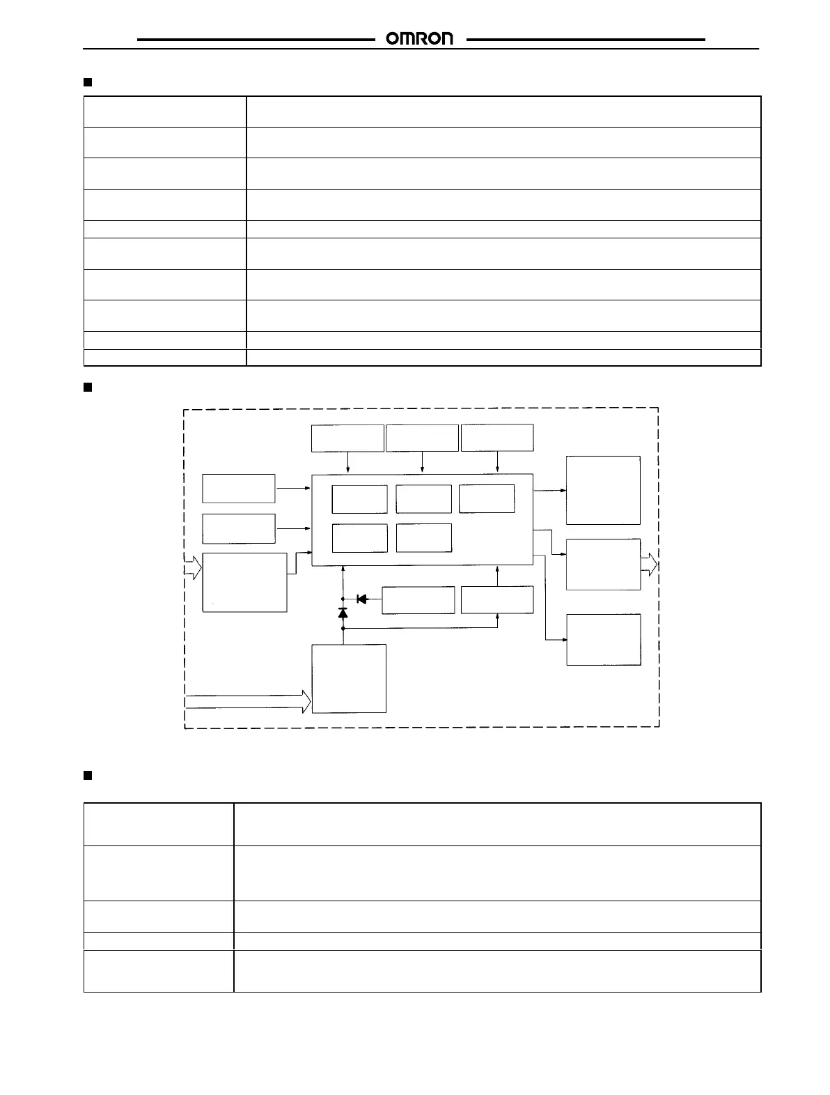
Block Diagram
Counter clock
generator
Function
setting circuit
ROM RAM LCD driver
Count
circuits
System clock
generator
LCD reference
voltage generator
Key switch
circuits
Input circuits
(count 1 to 9,
reset, re-monitor,
output number
request, I/O inhibit)
Count
circuits
One-chip
microcomputer
LCD
Output circuits
(Output 1 to 9,
RUN, machine
stoppage)
LED
Battery
Power failure
detector
Power circuits*
(DC) input
Although
the input terminals are electrically insulated from the internal circuit, do not conduct
an insulation resistance test on these terminals.
I/O Functions
Inputs
Count
(1 to 9)
Input count values.
Used as time count input signals when Counter is used as timer
.
Maximum counting speed: 30 Hz (minimum signal width: 16.7 ms)
Reset
Resets displayed count (timing) value of a specified Counter
.
Counter under reset does not operate ad its output is turned OFF
.
Reset signal input during re-monitor input restores reset count (timing) value of the specified Counter
.
While reset signal is ON, RST indicator lights.
Re-monitor
Reset count (timing) value of specified Counter can be re-monitored, and restored by reset input.
While re-monitor signal is ON, RCV indicator lights.
Counter No. select
Specifies Counter whose count (timing) value is to be displayed.
I/O inhibit
Inhibits count inputs of all Counters.
T
urns OFF all forecast outputs, RUN outputs, and machine stoppage outputs.
While I/O inhibit signal is ON, INHB indicator lights.
 Loading...