H8BM
H8BM
12
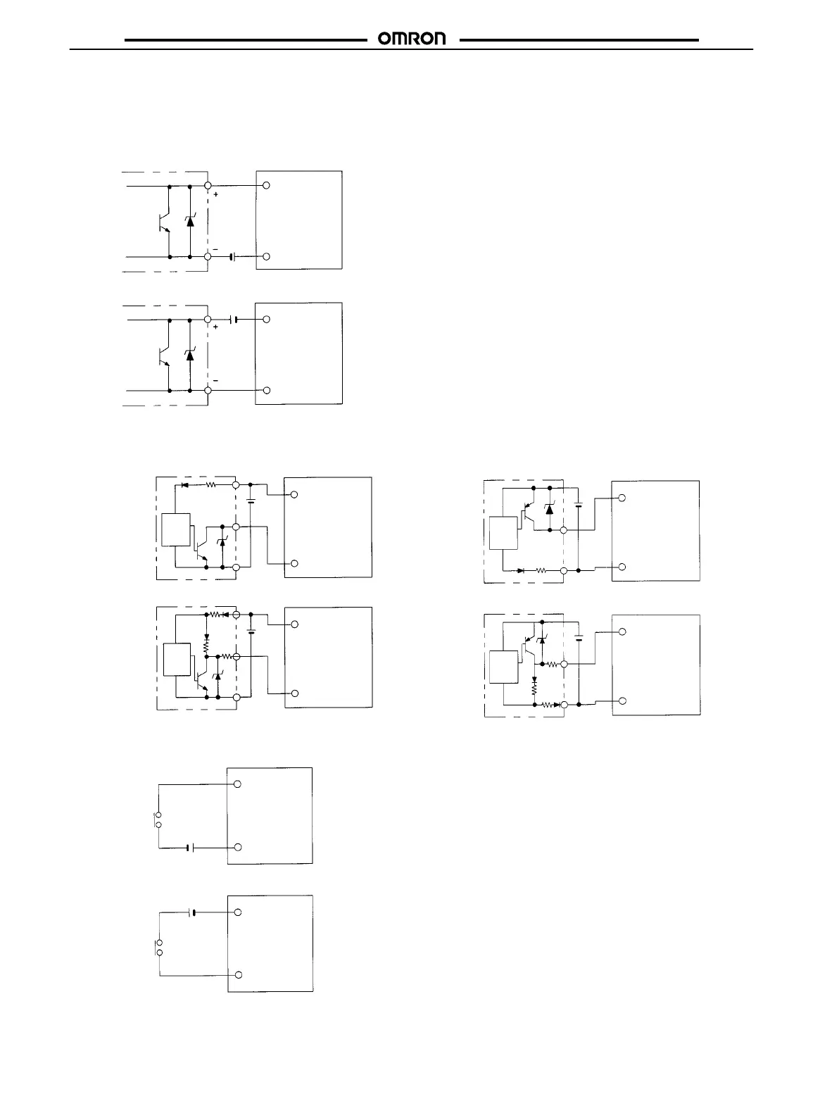
Example of Input Connections (Solid-state Switches)
Two-wire
Sensors
The
count input, counter No. select input,
reset input, I/O inhibit in
-
put, and re-monitor input signals are enabled when voltage is ap-
plied.
Two-wire sensor
IN COM
All inputs
H8BM
24 VDC
Two-wire sensor
All inputs
IN COM
H8BM
24 VDC
Note: Use
the following two-wire sensors:
1. High-level; transistor ON
Min. switching capacity: 5 mA max.
Residual voltage: 4 V max.
2.
Low-level: transistor OFF
Leakage current: 1.5 mA max.
3.
Power voltage range: 20.4 to 30 VDC
Use
of the OMRON TL-XD or E2E-XD-N Sensors is recommended.
Three-wire
Sensors
NPN Type PNP Type
Main
sensor
circuit
All inputs
COM
H8BM
Main
sensor
circuit
All inputs
COM
H8BM
Main
sensor
circuit
COM
All inputs
H8BM
Main
sensor
circuit
COM
All inputs
H8BM
Contact
Switch Connection
COM
All inputs
H8BM
All inputs
COM
H8BM
*H: Contact ON.
*Use contact that can break 13 mA, 30 V
 Loading...