7 SSI Input Units
7 - 12
NX-series Position Interface Units User’s Manual (W524)
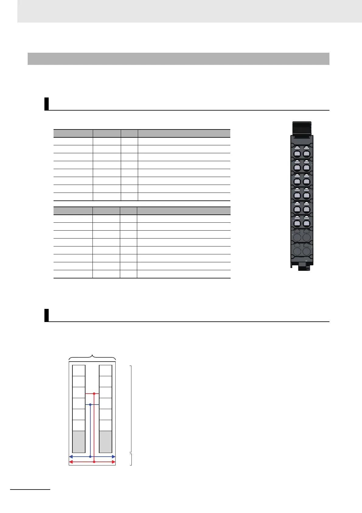
This section provides diagrams of the terminal block arrangement and internal power supply wiring of
the Two-input Unit. It also provides a wiring example.
A 12-terminal terminal block is used.
Note The SSI power supply output (24 V and 0 V) is provided power from the I/O power supply connected to the
Communications Coupler Unit or an Additional I/O Power Supply Unit.
The following diagram shows the internal power supply wiring.
7-5-2 NX-ECS212
Terminal Block Arrangement
Terminal No. Symbol I/O Name
A1 C1+ O Synchronous clock 1 output + side
A2 C1− O Synchronous clock 1 output − side
A3 IOV O SSI power supply output, 24 VDC
A4 IOG O SSI power supply output, 0 VDC
A5 C2+ O Synchronous clock 2 output + side
A6 C2− O Synchronous clock 2 output − side
A7 --- --- ---
A8 --- --- ---
Terminal No. Symbol I/O Name
B1 D1+ I SSI data input 1 + side
B2 D1− I SSI data input 1 − side
B3 IOV O SSI power supply output, 24 VDC
B4 IOG O SSI power supply output, 0 VDC
B5 D2+ I SSI data input 2 + side
B6 D2− I SSI data input 2 − side
B7 --- --- ---
B8 --- --- ---
Internal Power Supply Wiring Diagram
C1+ D1+
D1-
IOV
IOG
D2+
D2-
C1-
IOV
IOG
C2+
C2-
A B
A
B
1 1
2 2
3 3
4 4
5 5
6 6
7 7
8 8
24 V
0 V
C1+
C1-
IOV
IOG
C2-
C2+
D1+
D1-
IOV
IOG
D2+
D2-
Terminal block
NX bus connecto
SSI Input Unit
Note The I/O power is supplied from the I/O power supply connected
to the I/O power supply terminals on the Communications Cou-
pler Unit or an Additional I/O Power Supply Unit.