NX-CSG/SL5/SI/SO
11
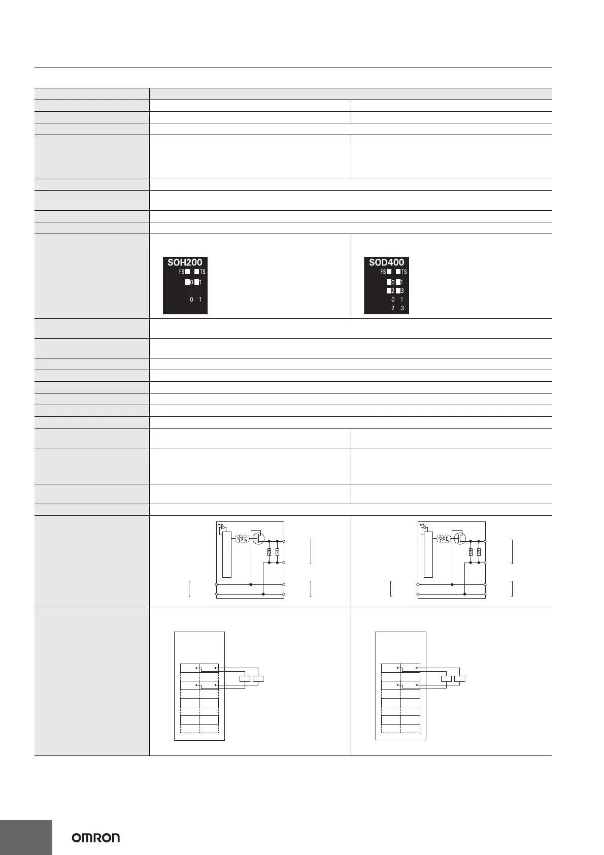
Safety Output Units NX-SOH200/SOD400
Unit name Safety Output Unit
Model NX- SOH200 NX- SOD400
Number of safety output points 2 points 4 points
Internal I/O common PNP (sourcing outputs)
Maximum load current
2.0 A/point
4.0 A/Unit at 40°C
2.5 A/Unit at 55°C
The maximum load current depends on the installation
orientation and ambient temperature
0.5 A/point and 2.0 A/Unit
Rated voltage 24 VDC (20.4 to 28.8 VDC)
Number of safety slave
connections
1
I/O refreshing method Free-Run refreshing
External connection terminals Screwless clamping terminal block (8 terminals)
Indicators
TS indicator, FS indicator, output indicators (yellow), and
output error indicators (red)
TS indicator, FS indicator, output indicators (yellow), and
output error indicators (red)
Safety output ON residual
voltage
1.2 V max. (Between IOV and all output terminals)
Safety output OFF residual
voltage
2 V max. (Between IOG and all output terminals)
Safety output leakage current 0.1 mA max.
Dimensions 12 × 100 × 71 mm (W × H × D)
Isolation method Photocoupler isolation
Insulation resistance 20 M min. between isolated circuits (at 100 VDC)
Dielectric strength 510 VAC for 1 min between isolated circuits, leakage current: 5 mA max.
I/O power supply method Power supplied from the NX bus
Current capacity of I/O power
supply terminals
IOG: 2 A max./terminal
IOG (A3 and B3): 2 A max./terminal
IOG (A7 and B7): 0.5 A max./terminal
NX Unit power consumption
• Connected to a CPU Unit or a Communication Control Unit
1.05 W max.
• Connected to a Communications Coupler Unit
0.70 W max.
• Connected to a CPU Unit or a Communication Control Unit
1.10 W max.
• Connected to a Communications Coupler Unit
0.75 W max.
Current consumption from I/O
power supply
40 mA max. 60 mA max.
Weight 65 g max.
Circuit layout
Terminal connection diagram
So0 and So1: Safety output terminals
IOG: I/O power supply 0 V
Refer to User's manual (Cat. No. Z395) for details.
So0 to So3: Safety output terminals
IOG: I/O power supply 0 V
Refer to User's manual (Cat. No. Z395) for details.
So0 to So1
Terminal block
IOG
I/O power
supply +
I/O power
supply −
Left-side NX
bus connector
I/O power
supply +
I/O power
supply −
Right-side NX
bus connector
Internal circuits
So0 to So3
Terminal block
IOG
I/O power
supply +
I/O power
supply −
Left-side NX
bus connector
I/O power
supply +
I/O power
supply −
Right-side NX
bus connector
Internal circuits
So0
A1 B1
A8 B8
So1
LL
IOG IOG
NC NC
NC NC
NX-SOH200
Safety
Output Unit
So0
A1 B1
A8 B8
So1
LL
IOG IOG
So2 So3
IOG IOG
NX-SOD400
Safety
Output Unit

 Loading...


