NX-CSG/SL5/SI/SO
6
Specifications of Individual Units
Communication Control Unit
*1. Includes the End Cover, and does not include projecting parts.
*2. Includes the End Cover. The weight of the End Cover is 82 g.
Unit name Communication Control Unit
Model NX-CSG320
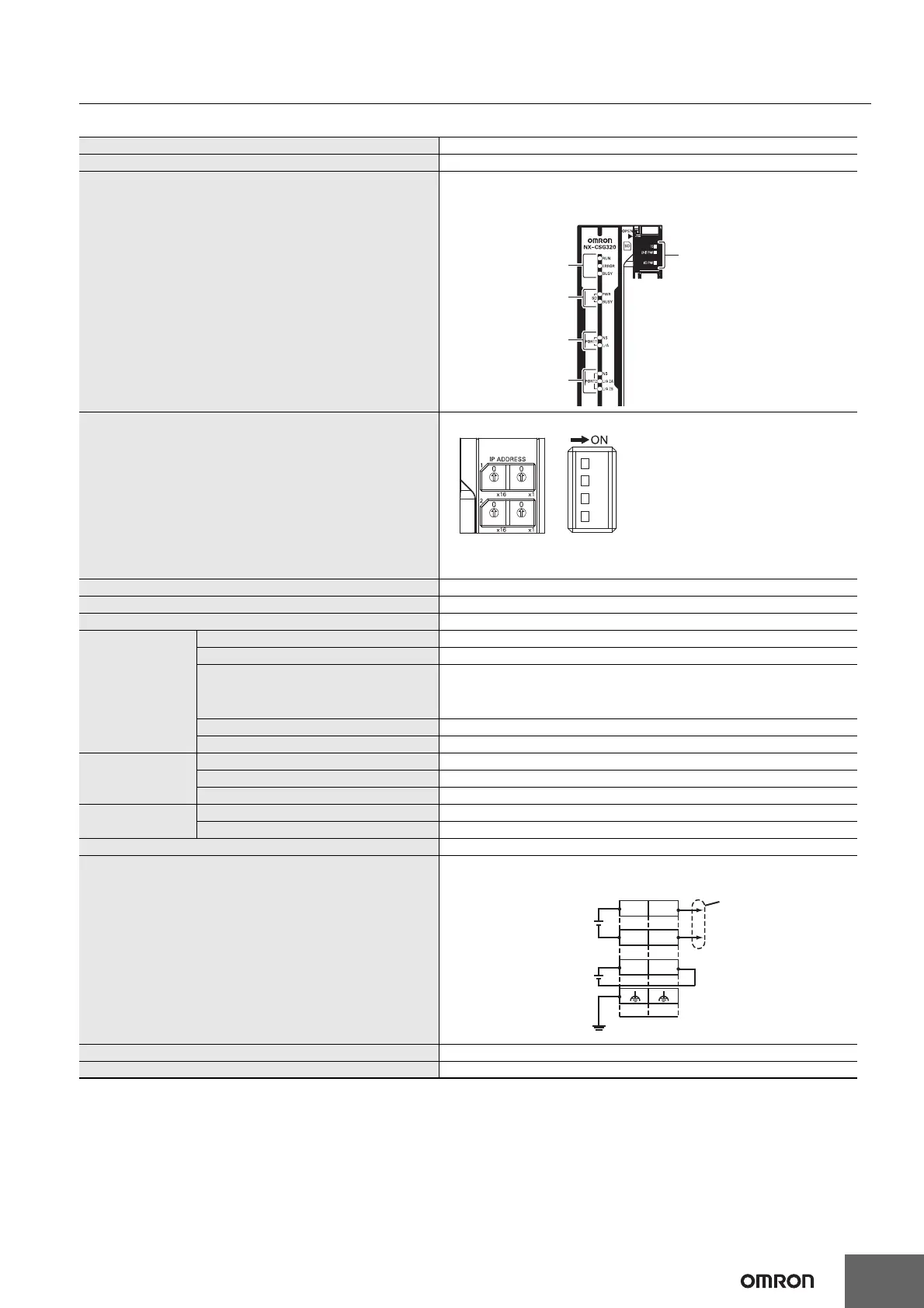
Indicators
[RUN] indicator, [ERROR] indicator, [BUSY] indicator, [SD PWR] indicator, [SD BUSY]
indicator, [NS] indicator × 2, [L/A] indicator, [L/A 2A] indicator, [L/A 2B] indicator, [TS]
indicator, [UNIT PWR] indicator, [I/O PWR] indicator
Hardware switch settings
[IP ADDRESS 1] Switch (x16, x1), [IP ADDRESS 2] Switch (x16, x1), DIP Switch
* Factory default
• IP ADDRESS1: 192.168.1.1 [IP ADDRESS 1] Switch = “00”
• IP ADDRESS2: 192.168.250.1 [IP ADDRESS 2] Switch = “00”
Dimensions *1 72 × 100 × 90 mm (W × H × D)
Weight *2 390 g
Number of NX Units that you can connect 32 units or less
Unit power supply
Power supply voltage 24 VDC (20.4 to 28.8 VDC)
Unit power consumption 5.95 W
Inrush current
For cold start at room temperature:
10 A max./0.1 ms max.
and
2.5 A max./150 ms max.
Current capacity of power supply terminal 4 A
Isolation method No isolation: Between the Unit power supply terminal and internal circuit
Power supply to the
NX Unit power
supply
NX Unit power supply capacity 10 W max.
NX Unit power supply efficiency 80%
Isolation method No isolation: Between the Unit power supply terminal and NX Unit power supply
I/O power supply to
NX Units
Power supply voltage 5 to 24 VDC (4.5 to 28.8 VDC)
Maximum I/O power supply current 4 A
External connection terminals Screwless clamping terminal block (8 terminals)
Terminal connection diagram
UV/UG: Unit power supply terminals
IOV/IOG: I/O power supply terminals
Accessories End cover (NX-END02): 1 pc.
Installation orientation and restrictions Only upright installation orientation
[SD PWR] indicator,
[SD BUSY] indicator
[TS] indicator,
[UNIT PWR] indicator,
[I/O PWR] indicator
[NS] indicator,
[L/A] indicator
[NS] indicator,
[L/A 2A] indicator,
[L/A 2B] indicator
[RUN] indicator,
[ERROR] indicator,
[BUSY] indicator
IOV
UG
UV
IOG
UV
UG
A1
A8
B1
B8
NXUnitpowersupply
(24VDC)
I/Opowersupply
(5to24VDC)
Groundof100Ω
orless
Through-wiringfor
unwiredterminals
 Loading...


